Shield with guide slot

A technology of guide grooves and shields, applied in the direction of defenses, etc., can solve the problems of throwing liquid splashing, insufficient ability, simplicity, etc., and achieve the effect of improving safety, comprehensive protection, and avoiding damage.

Active Publication Date: 2019-01-01
日照新睿招商发展有限公司
View PDF6 Cites 0 Cited by
  • Summary
  • Abstract
  • Description
  • Claims
  • Application Information

AI Technical Summary

Problems solved by technology

In the face of such attacks, the shields of the prior art used by law enforcers can generally resist the direct damage of the throwing liquid to the shield holder, but since the surface of the shield is a plane or arc surface, the throwing liquid will splash irregularly on the shield surface , the direction-changing throwing liquid can easily cause damage to other coordinated law enforcement personnel
[0009] In addition, the shields of the prior art also appear to have insufficient ability when attacking criminals as weapons. Most of them are pure protective equipment, and it is urgent to enhance their attack capabilities to achieve both offensive and defensive effects.

Method used


Image

  • Shield with guide slot
  • Shield with guide slot
  • Shield with guide slot

Examples


Embodiment 1

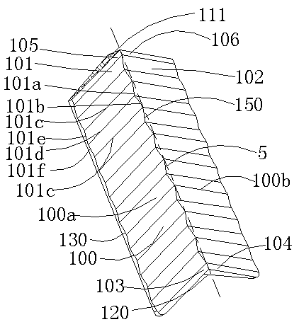
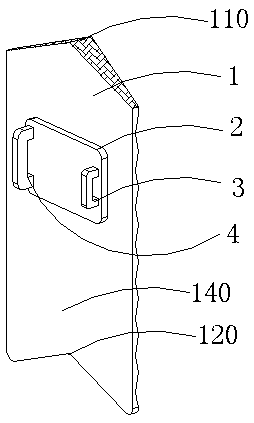
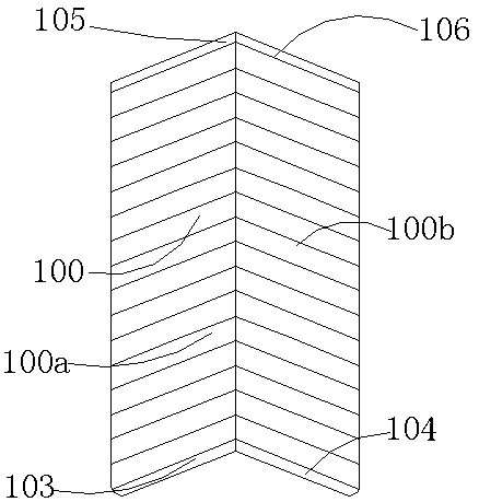
[0037] Embodiment 1: as Figure 1-5 As shown, a shield with a guide groove includes a shield body 1, a handle 4, a pad 2 and an elbow locking and fixing device 3. The shield body 1 includes a shield body front 100 and a shield body back 140. The pad 2 is connected to the shield body back 140, the handle 4 and the elbow locking fixture 3 are connected to the shield body 1 through the pad 2, and the shield body front 100 has a transverse cross-sectional shape of outer A convex surface, the convex surface may be an inverted V-shaped surface or an arc surface, or may be a convex trapezoid or other convex shapes. The convex surface can effectively unload the attack power and protect the shield holder when under attack.

[0038] Such as Figure 1-5As shown, the front of the shield body is provided with a left guide groove group 100a and a right guide groove group 100b, the left guide groove group 100a is composed of a plurality of continuous left guide grooves 101 to form a wrinkl...

Embodiment 2

[0046] Embodiment 2: as Figure 7 as shown, Figure 7 Numeral labels for geometric structures in figure 1 The corresponding numerals in are the same, indicating that the structure of the same numerals in Example 2 and Example 1 is basically the same. A shield with a guide groove, comprising a shield body 1, a handle 4, a pad 2 and an elbow locking fixture 3, the shield body 1 includes a shield body front 100 and a shield body back 140, the pad 2 It is connected to the shield body back 140, the handle 4 and the elbow locking fixture 3 are connected to the shield body 1 through the pad 2, and the shield body front 100 has a transverse cross-sectional shape that is convex, so The convex surface may be an inverted V-shaped surface or an arc surface, or a convex trapezoid or other convex shapes. In addition, the convex surface can effectively unload the attack power and protect the shield holder when under attack.

[0047] Such as Figure 7 As shown, the front of the shield bo...


PUM


Abstract

The invention discloses a shield with a guide slot, and relates to the field of police shields. The shield comprises a shield body, a holding handle, a protection pad and an elbow locking fixing device, wherein the shield body comprises a shield body front surface and a shield body back surface; the protection pad is connected with the shield body back surface; the holding handle and the elbow locking fixing device pass through the protection pad and are connected with the shield body; the cross section of the shield body front surface is in the shape of an outer convex surface; a left side guide slot group and a right side guide slot group are arranged on the shield body front surface; the left side guide slot group consists of a plurality of left side guide slots; the right side guide slot group consists of a plurality of right side guide slots; the left side guide slots upwards extend along the surface of the outer convex surface in an inclined mode from the left side edge of the shield body front surface; and the right side guide slots upwards extend along the surface of the outer convex surface in the inclined mode from the right side edge of the shield body front surface.

Description

[0001] This application is a divisional application of an invention patent application titled: A multifunctional shield with a guide groove, the application date is: March 5, 2017, and the application number is: 201710125754.3. technical field [0002] The invention relates to a shield, in particular to a police shield with a guide groove. Background technique [0003] Shields are an ancient defensive weapon. Soldiers holding shields can effectively block the enemy's weapons and protect their own lives. In ancient combat, whether in the history of China, ancient Greece or ancient Rome, the shield is a very important weapon for tactical use and has been developed to this day. Although the glory of the shield in military use no longer exists today, the shield has a new life in the field of modern police use. In the current atmosphere where the world pattern tends to be peaceful, large-scale wars are unlikely to occur, but individual criminal activities within the country freq...

Claims


Application Information

Patent Timeline
Patent Type & Authority Applications(China)
IPC IPC(8): F41H5/08
CPCF41H5/08
Inventor 曾国庆
Owner 日照新睿招商发展有限公司
Why Eureka
Try Eureka