Multifunctional shield with S-shaped guiding grooves

一种导向槽、盾牌的技术,应用在防御物等方向,能够解决伤害、抛掷液体飞溅等问题,达到避免造成伤害、减缓滑动速度、增加滑动阻力的效果

Active Publication Date: 2019-02-15
SHAOXING COUNTY FULIN TEXTILE CO LTD
View PDF6 Cites 0 Cited by
  • Summary
  • Abstract
  • Description
  • Claims
  • Application Information

AI Technical Summary

Problems solved by technology

In the face of such attacks, the shields of the prior art used by law enforcers can generally resist the direct damage of the throwing liquid to the shield holder, but since the surface of the shield is a plane or arc surface, the throwing liquid will splash irregularly on the shield surface , changing directions, throwing liquids can easily cause harm to other law enforcement officers in coordination

Method used


Image

  • Multifunctional shield with S-shaped guiding grooves
  • Multifunctional shield with S-shaped guiding grooves
  • Multifunctional shield with S-shaped guiding grooves

Examples


Embodiment 1

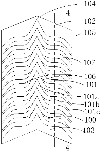
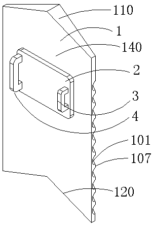
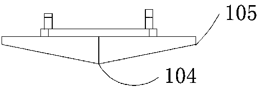
[0032] Embodiment 1: as Figure 1-4 As shown, a multifunctional shield with an S-shaped guide groove includes a shield body 1, a handle 4, a pad 2 and an elbow locking and fixing device 3, and the shield body 1 includes a shield body front 100 and a shield body back 140, the pad 2 is connected to the back side 140 of the shield body, the handle 4 and the elbow locking fixture 3 are connected to the shield body 1 through the pad 2, and the front side of the shield body 100 has a transverse section Contains a vertex and two side points, the vertex forms the vertex intersection line 104, the side points form the side point intersection line 105, the height of the vertex intersection line 105 gradually decreases and extends to the side point intersection line 110 to form the side surface 106, the The shield body front 100 is axially symmetrical along the vertex intersection line 104, and the shield body front 100 is a convex arc surface, an inverted V-shaped surface or an arc surf...

Embodiment 2

[0043] Such as Image 6 As shown, in this embodiment, the groove body 101b is optimized on the basis of Embodiment 1. The groove body 101b includes the groove edge 101b1 and the groove edge 101b2. When the groove body 101b extends from the groove head 101a to the groove tail 101c , the vertical height gradually decreases, and the vertical height refers to the distance perpendicular to the shield tail 120 at any point on the slot edge 101b1. At the same time, the groove side 101b1 and the groove side 101b2 gradually approach when extending from the groove head 101a to the groove tail 101c, so when the groove body 101b extends along the groove head 101a to the groove tail 101c, the opening size of the groove body 101b gradually decrease.

[0044] In this embodiment, for projectiles or liquids, the shield can have an effect similar to that of Embodiment 1, which will not be repeated here. In this embodiment, when attacking with sticks, one of the motion trajectories is as follo...


PUM


Abstract

The invention discloses a shield with S-shaped guiding grooves. The shield comprises a shield body; a transverse section on the front face of the shield body comprises a vertex and two side points, avertex intersecting line is composed of the vertex, side point intersecting lines are composed of the side points, and side edges are composed of the positions from the vertex to the side points, theheight of the vertex intersecting line is gradually decreased, the vertex intersecting line extends to the side point intersecting lines to form the side faces, and the front face of the shield body is axially symmetrical along the vertex intersecting line; the side faces comprise the guiding grooves and guiding ridges, the guiding grooves comprise groove heads, groove bodies and groove tails, thegroove bodies are formed by transversely extending from the groove heads in the vertex intersecting line to the groove tails in the side point intersecting lines, and the groove bodies are each arranged to be in an S shape; and the guiding ridges are arranged between the two adjacent guiding grooves, the S shape of each groove body comprises a complete S shape or partial S shape, or multiple continuous S shapes, the S-shaped groove bodies are internally provided with protruding points, or the S-shaped groove bodies are arranged to be friction faces, thus the sliding distance and the sliding resistance are effectively increased, the impact force to shield holding personnel is relieved, and the sliding speed of attaching objects is decreased.

Description

[0001] This application is a divisional application of an invention patent application titled: A multifunctional shield with an S-shaped guide groove, the application date is: March 5, 2017, and the application number is: 201710125740.1. technical field [0002] The invention relates to a shield, in particular to a police shield with guiding protection function. Background technique [0003] Shields are an ancient defensive weapon. Soldiers holding shields can effectively block the enemy's weapons and protect their own lives. In ancient combat, whether in the history of China, ancient Greece or ancient Rome, the shield is a very important weapon for tactical use and has been developed to this day. Although the glory of the shield in military use no longer exists today, the shield has a new life in the field of modern police use. In the current atmosphere where the world pattern tends to be peaceful, large-scale wars are unlikely to occur, but individual criminal activities ...

Claims


Application Information

Patent Timeline
Patent Type & Authority Applications(China)
IPC IPC(8): F41H5/08
CPCF41H5/08
Inventor 曾国庆
Owner SHAOXING COUNTY FULIN TEXTILE CO LTD
Why Eureka
Try Eureka