
Equal-flow area conical screw-sleeve pair

A flow area, conical screw technology, applied in the direction of rotary piston machinery, machine/engine, rotary piston pump, etc., can solve the problem of no way to process, increase the instability of flow, large pressure pulsation, etc.

Inactive Publication Date: 2017-05-10
BEIJING UNIV OF TECH
View PDF7 Cites 5 Cited by
  • Summary
  • Abstract
  • Description
  • Claims
  • Application Information

AI Technical Summary

Problems solved by technology

In the patent document CN 103883522 A and the patent document CN 103775334 A, the flow area of ​​each cross-section of the proposed conical screw bush pair from the inlet end to the outlet end is continuously reduced, and the volume of each cavity is rapidly reduced accordingly, resulting in The displacement of the pump is small, the pressure pulsation between the chambers is large, and the flow is not stable, which seriously affects the normal operation and service life of the pump.
In the patent document WO 2010100134 A2, a conical screw bushing pair with equal volumes is proposed. The volume of each cavity is equal. The realization method is through the combination of a series of parameters such as eccentricity and rotor diameter. The volume of each cavity is made equal, but the flow area of ​​each cross-section from the inlet end to the outlet end of this conical screw bushing pair is not constant, which increases the flow instability. At the same time, the patent does not give There is no way to process and manufacture the specific surface equations of the cone-screw and the cone-shaped bushing, which affects the promotion and use of the cone-screw pump

Method used


Image

  • Equal-flow area conical screw-sleeve pair
  • Equal-flow area conical screw-sleeve pair
  • Equal-flow area conical screw-sleeve pair

Examples


Embodiment Construction

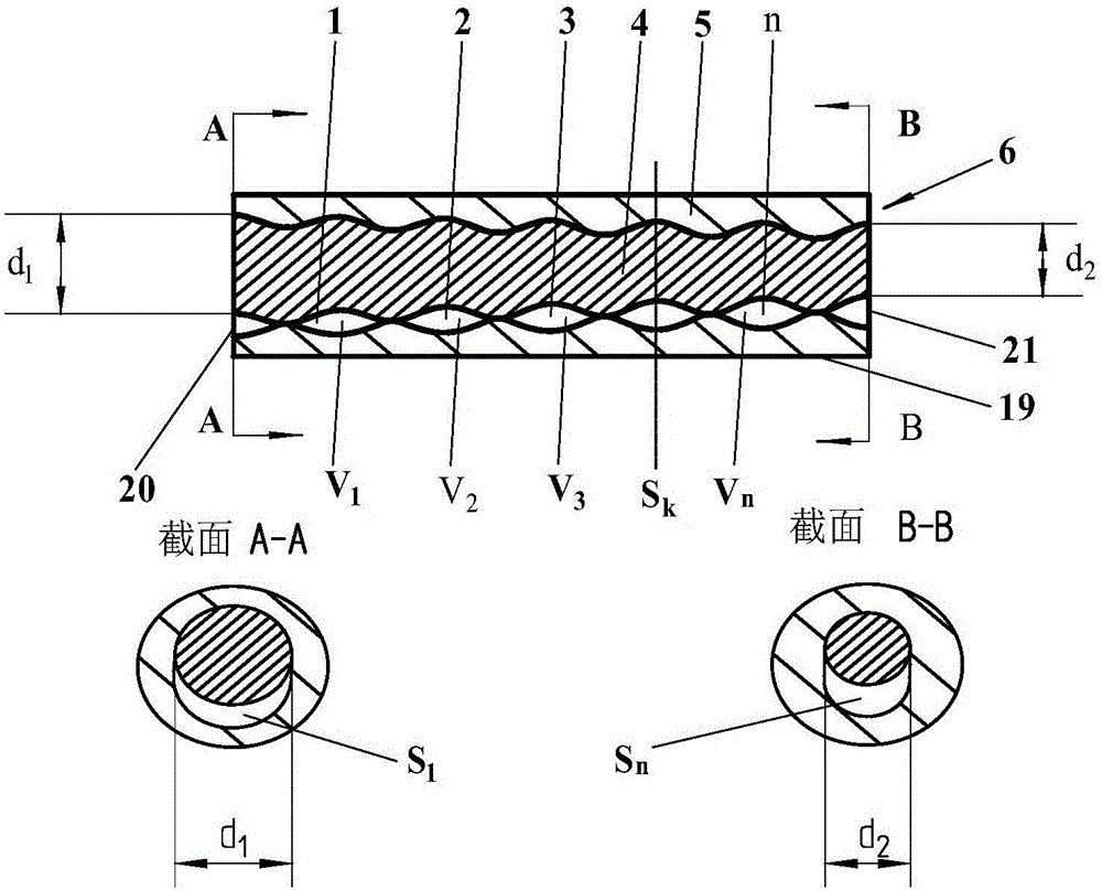
[0048] Such as Figure 1-6 Shown, a kind of conical screw-bush pair, it comprises conical screw rod 4, conical bushing 5; The tapered bushing 5 comprises a tapered bushing inner curved surface 16, a tapered bushing large end face 17, a tapered bushing small end face 18 and a tapered bushing outer cylindrical surface 19; the tapered screw large end face 10 and the cone The large end face 17 of the tapered bush forms the inlet end 20 of the tapered screw-bush pair; the small end face 11 of the tapered screw and the small end face 18 of the tapered bush form the outlet end 21 of the tapered screw-bush pair.

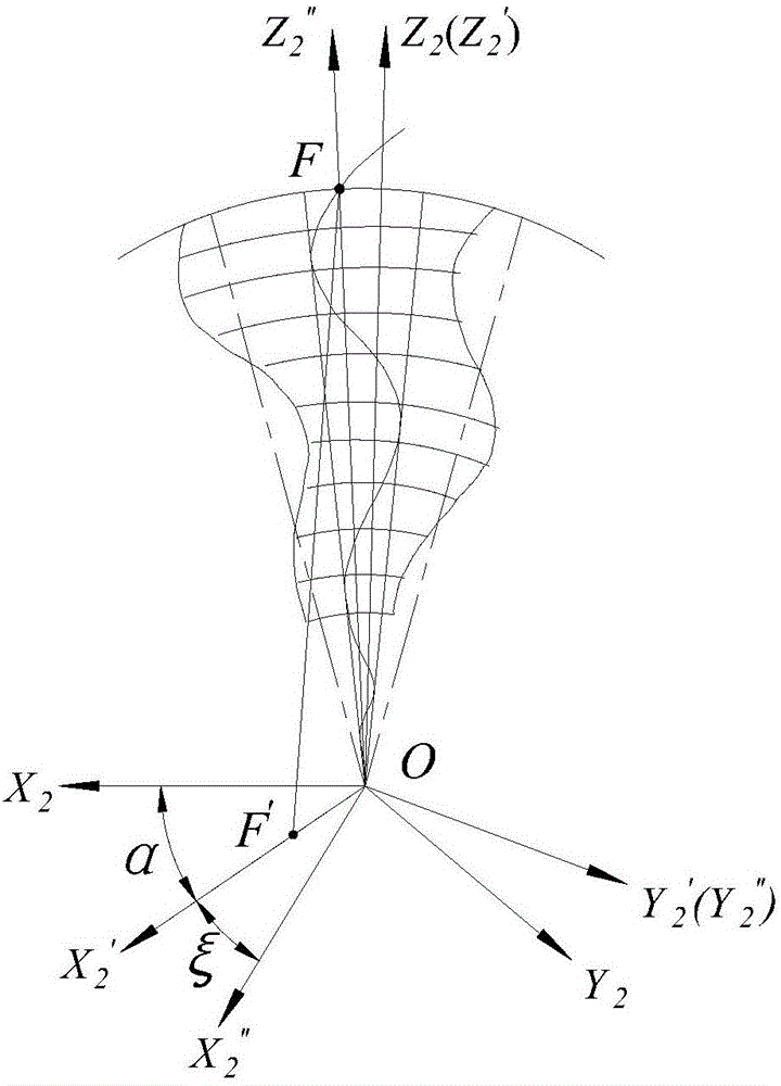
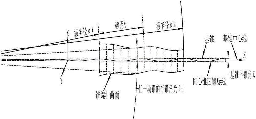
[0049] Based on the curved surface forming method of the traditional conical screw-bush pair, the proposed curved surface forming method of the new single-headed conical screw-bush pair (6) includes: the forming method of the S1 conical screw curved surface 9 and the S2 conical bush curved surface 16. Shaping method.

[0050] Curved Surface Forming Method of S1 Conical Scr...


PUM


Abstract

The invention discloses an equal-flow area conical screw-sleeve pair, which belongs to the application field of single-screw pumps. A conical sleeve comprises an inner curved conical sleeve surface, a big conical sleeve end surface, a small conical sleeve end surface, and an outer cylindrical conical sleeve surface; a big conical screw end surface and the big conical sleeve end surface compose an inlet end of the conical screw-sleeve pair; and a small conical screw end surface and the small conical sleeve end surface compose an outlet end of the conical screw-sleeve pair. The flow area of one section of the conical screw-sleeve pair is defined as a difference between the area of the inner curved conical sleeve surface and the area of an outer curved conical screw surface in the section. The equal-flow area characteristic and equal-cavity characteristic of the conical screw-sleeve pair can help increase the displacement of a single-head conical screw pump and reduce pressure fluctuation, so that flow is smoother; moreover, pressure rise from the inlet end to the outlet end is relatively small, relative sliding speed is low in the process of movement, consequently, abrasion is reduced, and the service life is prolonged.

Description

technical field [0001] The invention relates to the application field of single-screw pumps, in particular to a method for forming a curved surface of a tapered screw-bush pair, capable of transporting very viscous media, all media containing water, media containing gas, and media containing fibers and solid particles. Medium, etc., can be used in petroleum, chemical, pharmaceutical and other fields. Background technique [0002] The traditional cone-screw-sleeve pairs widely used in single-head cone-screw pumps are mostly cavity-reducing structures. Rotating, the working medium is continuously conveyed from the inlet end of the conical screw-bush pair to the outlet end. There are many defects and problems in some existing tapered screw rod-bush pairs. In the patent document CN 103883522 A and the patent document CN 103775334 A, the flow area of ​​each cross-section of the proposed conical screw bush pair from the inlet end to the outlet end is continuously reduced, and th...

Claims


Application Information

Patent Timeline
IPC IPC(8): F04C2/107
CPCF04C2/107F04C2/1073F04C2/1075
Inventor 王新华王云琨陈迎春涂承媛贺燕军赵以振张涛
Owner BEIJING UNIV OF TECH
Learn More