A Modeling Method for Encoded Mask Optical Imaging System

An optical imaging system and imaging system technology, applied in special data processing applications, instruments, electrical digital data processing, etc., can solve the problems of complicated operation process, and achieve the effect of avoiding operation errors and simplifying the process.

Inactive Publication Date: 2017-02-15
TIANJIN UNIV
View PDF2 Cites 0 Cited by
  • Summary
  • Abstract
  • Description
  • Claims
  • Application Information

AI Technical Summary

Problems solved by technology

This method is intuitive and accurate, but the optical system design and optimization process often requires repeated testing to obtain imaging results, making the operation process complicated

Method used


Image

  • A Modeling Method for Encoded Mask Optical Imaging System
  • A Modeling Method for Encoded Mask Optical Imaging System
  • A Modeling Method for Encoded Mask Optical Imaging System

Examples


Embodiment Construction

[0052] A modeling method for an encoding mask optical imaging system of the present invention will be described in detail below in conjunction with embodiments and drawings.

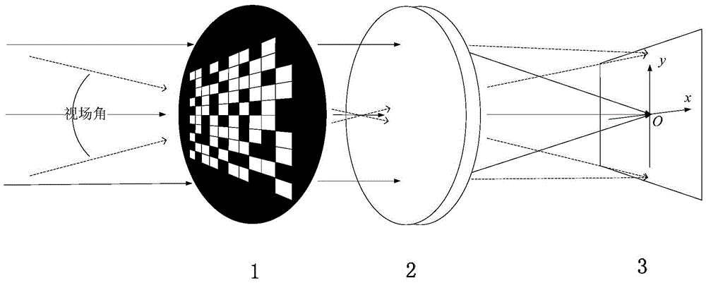
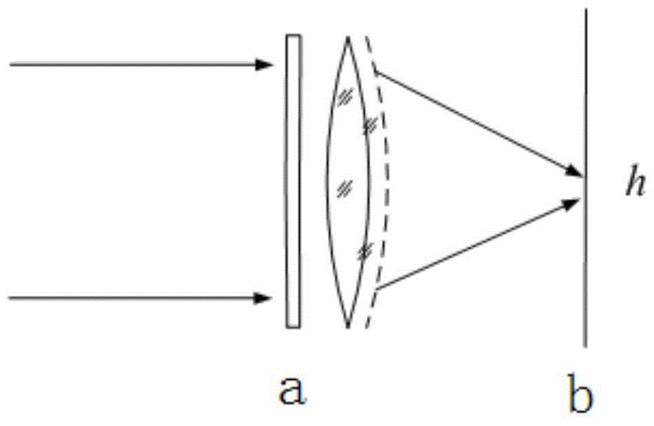
[0053] The coded mask imaging system is obtained by placing a light baffle that blocks the incident light at the position immediately before the lens group of the traditional optical imaging system. The whole system structure is as follows: figure 1 shown. The light baffle has a certain code structure, which can modulate the incident light, so it is also called a code mask. The final imaging result obtained by the detector is the combined result of the modulation of the original scene by the encoding mask and the actual convergence of the light by the lens group.

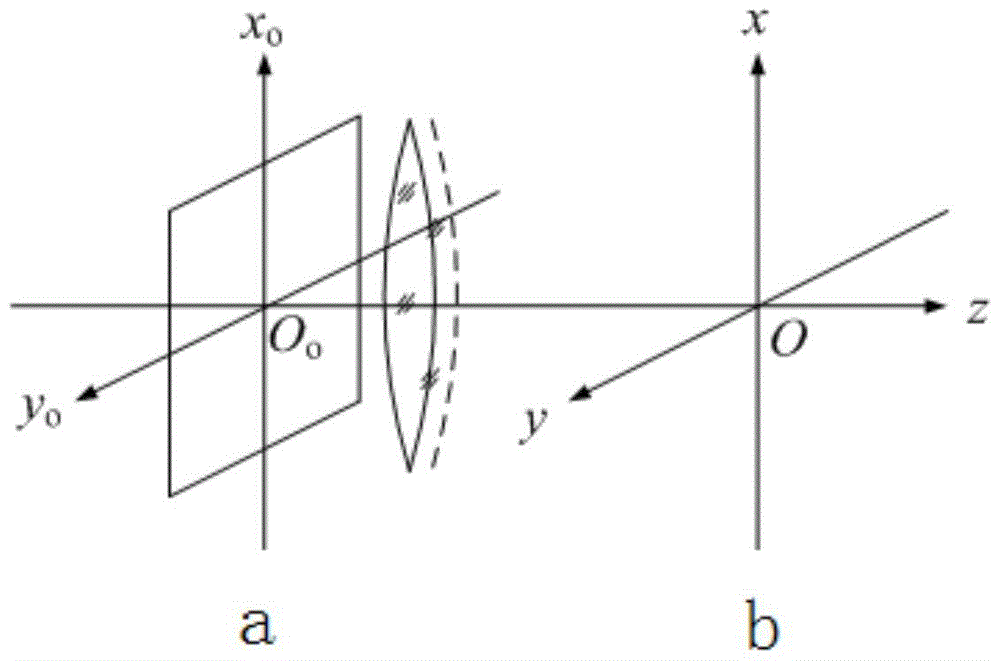
[0054] A modeling method of an encoding mask optical imaging system of the present invention is to describe the imaging process of the entire system according to the structure of the encoding mask and the transfer function of the lens group, ...


PUM


Abstract

A modeling method for a coded mask optical imaging system includes: according to a structure of a coded mask imaging system, obtaining a basic model of the whole coded mask imaging system on the basis of an imaging principle of the coded mask imaging system; regarding the basic model of the whole coded mask imaging system as being formed by cascade connection of two modules; substituting a point spread function in the basic model, formed by cascade connection of two modules, of the whole coded mask imaging system into the basic model of the whole coded mask imaging system to obtain a model of the whole coded mask imaging system: g(x, y)=h1(x, y)*h2(x, y)*go(x, y)+n(x, y). By adoption of the modeling method, the point spread function of the system can be obtained more conveniently and rapidly, a preparation process of manufacturing, constructing and adjusting a real system is omitted, and possible operation errors in actual measurement are avoided; further, a significant instruction function can be provided for structural design of the coded mask imaging system, especially for code pattern design of coded masks so as to facilitate further theoretical research and promotion on the basis of the model.

Description

technical field [0001] The invention relates to a modeling method of an encoding mask optical imaging system. In particular, it relates to a modeling method of an encoding mask optical imaging system for describing the transmission characteristics of a lens system and a mask structure in the encoding mask optical imaging system. Background technique [0002] The coded mask imaging system originated in the detection and imaging process of heavy particle rays such as X-rays. Since the long-distance heavy particle rays cannot be focused on the detector by the traditional optical lens system, a code mask with a certain pattern structure is used to modulate the heavy particle rays reaching the detection system, and the detection results need to be coordinated. Corresponding image decoding techniques are used to restore and image the original heavy particle radiation source scene (E.E. Fenimore, and T.M. Cannon, "Coded aperture imaging with uniformly redundant arrays," ApplOptics...

Claims


Application Information

Patent Timeline
Patent Type & Authority Patents(China)
IPC IPC(8): G06F17/50
Inventor 张傲汪清金杰杨敬钰孙懿
Owner TIANJIN UNIV
Why Eureka
Try Eureka