Anti-seismic steel support for bridge

A technology of anti-seismic steel and bridges, which is applied in the direction of bridges, bridge parts, bridge construction, etc., and can solve the problem of single function and scope of application of anti-seismic bearings, and the bearings are prone to tension, poor tensile capacity or anti-vertical lift-off ability and other problems, to achieve strong anti-vertical lift-off ability, reduce beam end collision damage, and greatly promote the effect of application prospects

Inactive Publication Date: 2017-06-30
SOUTHWEST JIAOTONG UNIV
View PDF6 Cites 1 Cited by
  • Summary
  • Abstract
  • Description
  • Claims
  • Application Information

AI Technical Summary

Problems solved by technology

[0003] The existing anti-seismic bearings of bridge structures include lead rubber bearings, high damping rubber bearings, anti-seismic basin bearings and friction pendulum bearings; it is not difficult to find that the bridge superstructure still has lateral limit Insufficient torsion resistance, insufficient longitudinal limit, etc. lead to the collision and spalling of the end of the main beam of the bridge structure, the damage of the transverse limit block and the accident of falling beams; under the action of a large vertical earthquake, the support of the bridge structure The seat is prone to tension; the above-mentioned types of anti-seismic bearings have relatively poor tensile strength or anti-vertical lift-off ability, which can easily lead to the support being empty; and the existing bridge anti-seismic bearings have relatively single functions and scope of application. , in order to achieve multi-function often need to cooperate with a variety of shock-absorbing measures, which will lead to a significant increase in cost

Method used


Image

  • Anti-seismic steel support for bridge
  • Anti-seismic steel support for bridge
  • Anti-seismic steel support for bridge

Examples


Embodiment Construction

[0021] The present invention will be further described below with reference to the accompanying drawings and specific embodiments.

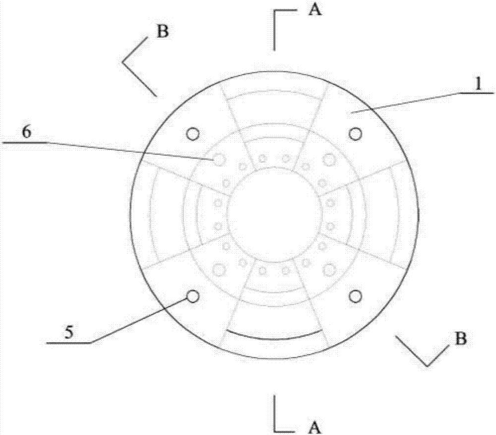
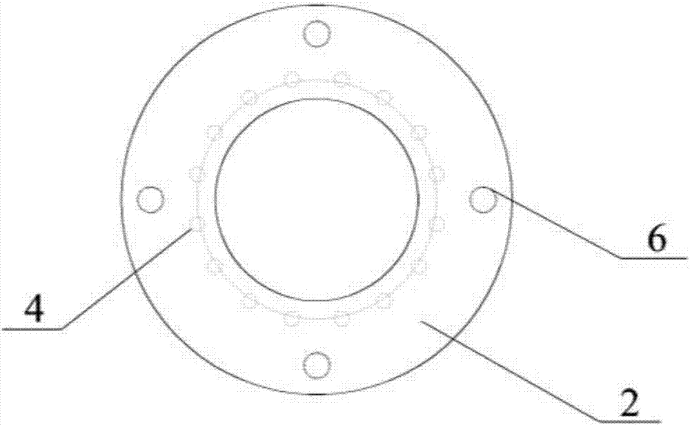
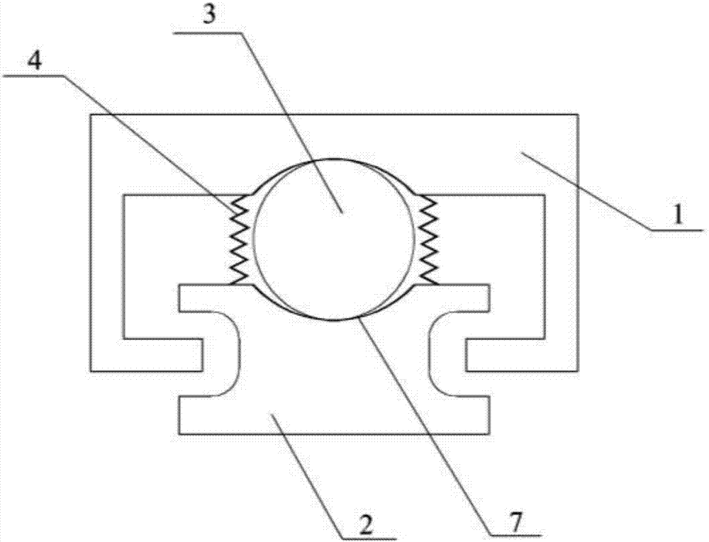
[0022] like Figure 1-4 As shown in the figure, an anti-seismic steel bearing of a bridge includes an upper bearing body 1 connected with the main beam of the bridge and a lower bearing body 2 connected with the bridge cover beam or pier; it also includes a steel sphere 3, which is arranged on the upper bearing between the body 1 and the lower support body 2; the upper support body 1 is provided with a concave arc-shaped upper connecting portion that matches the rigid sphere 3 at the position corresponding to the steel ball 3, and the lower support body 2 is provided at the position corresponding to the steel ball 3 There is a concave arc-shaped lower connecting part that matches the rigid ball 3; a spring 4 is arranged between the upper support body 1 and the lower support body 2, which can move relatively; the surfaces of the upper connecting p...


PUM


Abstract

The invention discloses a anti-seismic steel support for a bridge. The anti-seismic steel support for a bridge comprises an upper support body connected with a bridge main beam and a lower support body which is connected with a bridge cover beam or a pier abutment; the anti-seismic steel support for the bridge further comprises a steel ball body which is arranged between the upper support body and the lower support body; a concave-arc-shaped upper connecting part, which is matched with the steel ball body, is arranged at a position, corresponding to the steel ball body, of the upper support body; a concave-circular-arc-shaped lower connecting part, which is matched with the steel ball body, is arranged at a position, corresponding to the steel ball body, of the lower support body; a spring is arranged between the upper support body and the lower support body and can move relatively; and wear-resisting layers are arranged on surfaces of the upper support body and the lower support body. The anti-seismic steel support for thebridge disclosed by the invention is simple in structure, clear in force transmission path and small in manufacturing and machining difficulty; and the support can have various functions of self-resetting, multidirectional limitation, vertical lifting prevention capability and the like.

Description

technical field [0001] The invention relates to the technical field of bridge anti-seismic and bridge seismic isolation, in particular to a bridge anti-seismic steel bearing. Background technique [0002] Each earthquake will lead to the loss of my country's national economy to varying degrees, and cause certain damage to bridge structures, housing buildings and hydraulic dams. It has brought great obstacles. How to ensure the safety of the bridge structure and reduce the earthquake disaster and secondary disaster of the bridge structure, how to choose a reasonable bridge structure seismic system and seismic isolation measures for the high-intensity area of ​​seismic fortification has always been a bridge structure. A hot research topic in the field of seismic engineering. [0003] The existing seismic bearings of bridge structures include lead rubber bearings, high damping rubber bearings, anti-seismic basin bearings and friction pendulum bearings; it is not difficult to fin...

Claims


Application Information

Patent Timeline
IPC IPC(8): E01D19/04
CPCE01D19/046
Inventor 赵人达廖平徐腾飞占玉林贾毅王永宝杨世玉崔玲枝
Owner SOUTHWEST JIAOTONG UNIV
Why Eureka
Try Eureka