Combined frame

A frame and frame structure technology, which is applied to fixed grilles, shutters/movable grilles, windows/doors, etc., can solve the problems of scratching and wearing of window sash and window frame, difficulty in closing sash, and affecting service life, etc., to achieve Solve the difficulty of opening and closing, improve the service life, and prevent the effect of scratching and wearing

Active Publication Date: 2017-06-30
HUNAN GOLDWELL NEW MATERIALS TECH CO LTD
View PDF5 Cites 0 Cited by
  • Summary
  • Abstract
  • Description
  • Claims
  • Application Information

AI Technical Summary

Problems solved by technology

In the prior art, the window sash is generally hinged with the window frame to form an opening and closing structure. Since the window sash itself has a certain weight, after repeated opening and closing or opening for a long time, the window sash will fall to a certain extent due to its own weight, causing the window sash to close. Difficult, in severe cases, the window sash and window frame will be scratched and worn, which will affect its service life

Method used


Image

  • Combined frame
  • Combined frame
  • Combined frame

Examples


Embodiment 1

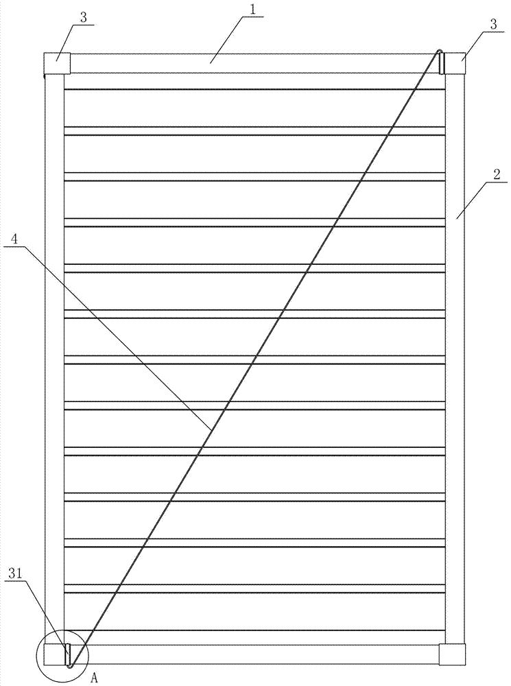
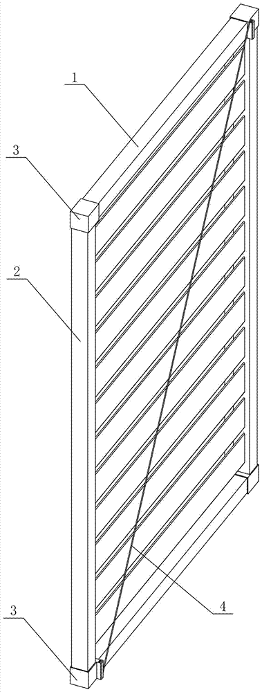
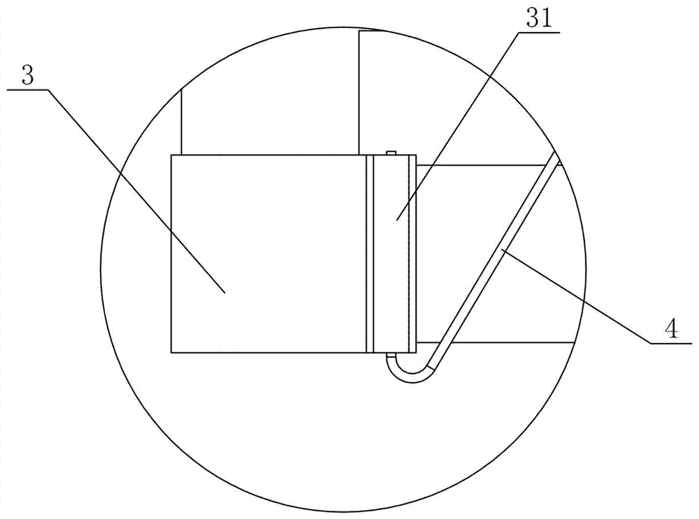
[0050] Figure 1 to Figure 5 Shows the first embodiment of the combined frame of the present invention, the combined frame includes a cross bar 1, a vertical bar 2 and a connecting joint 3, the horizontal bar 1 is provided with two upper and lower bars, and the vertical bar 2 is provided with two left and right bars, adjacent to each other The ends of the horizontal bar 1 and the vertical bar 2 are connected and enclosed by connecting joints 3 to form a frame structure, and at least one pair of connecting joints 3 located on the diagonal of the frame structure are provided with pull joints 31, located on the diagonal A stay cable 4 for preventing the frame structure from falling is connected between the two draw joints 31 . In this structure, the ends of adjacent cross bars 1 and vertical bars 2 are connected and enclosed by connecting joints 3 to form a frame structure, that is, the combined frame is assembled by connecting and assembling the cross bars 1, vertical bars 2 and...

Embodiment 2

[0056] Figure 6 to Figure 8 Shows the second embodiment of the composite frame of the present invention, the composite frame is basically the same as Embodiment 1, the difference is that: in this embodiment, the pull connection hole 311 is set as a threaded hole, and the two ends of the pull cable 4 are provided with pull Tighten the bolt 41, and tighten the bolt 41 to be threadedly connected with the threaded hole at the corresponding end. In this structure, by setting the tension connection hole 311 as a threaded hole, and setting tension bolts 41 at both ends of the drag cable 4, the tension installation can be completed only by tightening the tension bolts 41 at both ends, so that the tension can be obtained. It is controllable and also improves the convenience of installation.

[0057] In this embodiment, there is one pull connection portion 31 , and the pull connection hole 311 is parallel to the vertical rod 2 and located at the outer edge of the vertical rod 2 . Suc...

Embodiment 3

[0059] Figure 9 to Figure 11 Shows the third embodiment of the composite frame of the present invention, the composite frame is basically the same as Embodiment 2, the only difference is: in this embodiment, two pairs of pulls on the connecting joint 3 on the diagonal line of the frame structure The connecting parts 31 are all connected to the pull cables 4 , and there is one connecting part 31 for each connecting joint 3 . The connecting holes 311 are parallel to the cross bar 1 and located at the outer edge of the cross bar 1 . Such arrangement makes the combined frame indirectly receive the upward vertical component force of the connecting portion 31 while being subjected to the main force of the oblique pull of the cable 4, which greatly improves the tension strength.


PUM


Abstract

The invention discloses a combined frame which comprises upper and lower cross rods, left and right vertical rods and connecting joints. The ends of the adjacent cross rods and the adjacent vertical rods are connected through the connecting joints and form a frame structure in an enclosure mode, at least one pair of connecting joints located on the diagonal line of a frame structure is provided with pull-connecting portions, and pull cables are connected between the two pull-connecting portions located on the diagonal line. The combined frame has the advantages of being simple and compact in structure, convenient to install, long in service life, stable and reliable.

Description

technical field [0001] The invention mainly relates to the protection technology of building windows, in particular to a composite frame. Background technique [0002] Along with the continuous development of the entire social economy and the continuous improvement of living conditions, how to have a comfortable, safe and good rest and sleep environment is a problem that people are very concerned about. [0003] Existing protective windows, shutters, etc. can basically achieve the effects of preventing children from falling from the window, preventing theft, and ensuring privacy. In the prior art, the window sash is generally hinged with the window frame to form an opening and closing structure. Since the window sash itself has a certain weight, after repeated opening and closing or opening for a long time, the window sash will fall to a certain extent due to its own weight, causing the window sash to close. Difficulty, in severe cases, the window sash and window frame will...

Claims


Application Information

Patent Timeline
Patent Type & Authority Applications(China)
IPC IPC(8): E06B9/01E06B9/02E06B3/964E06B7/28
CPCE06B3/9647E06B7/28E06B9/01E06B9/02
Inventor 谢斌泉其他发明人请求不公开姓名
Owner HUNAN GOLDWELL NEW MATERIALS TECH CO LTD
Why Eureka
Try Eureka