
AGC (Automatic Gain Control) device for implementing dynamic range gain and radio frequency receiving circuit

A dynamic range, radio frequency receiving technology, applied in the field of communication, can solve the problems of radio frequency front-end saturation, signal distortion, large signal, etc.

Inactive Publication Date: 2017-07-04
AEROSPACE INFORMATION
View PDF5 Cites 9 Cited by
  • Summary
  • Abstract
  • Description
  • Claims
  • Application Information

AI Technical Summary

Problems solved by technology

In some cases, such as laboratory close-range testing or OBU close-range detection, the signal entering the RSU receiving link will be very large, which will easily cause the RF front-end to be saturated and cause signal distortion

Method used


Image

  • AGC (Automatic Gain Control) device for implementing dynamic range gain and radio frequency receiving circuit
  • AGC (Automatic Gain Control) device for implementing dynamic range gain and radio frequency receiving circuit
  • AGC (Automatic Gain Control) device for implementing dynamic range gain and radio frequency receiving circuit

Examples


Embodiment Construction

[0028] Specific embodiments of the present invention will be described in detail below in conjunction with the accompanying drawings. It should be understood that the specific embodiments described here are only used to illustrate and explain the present invention, and are not intended to limit the present invention.

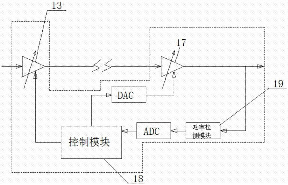
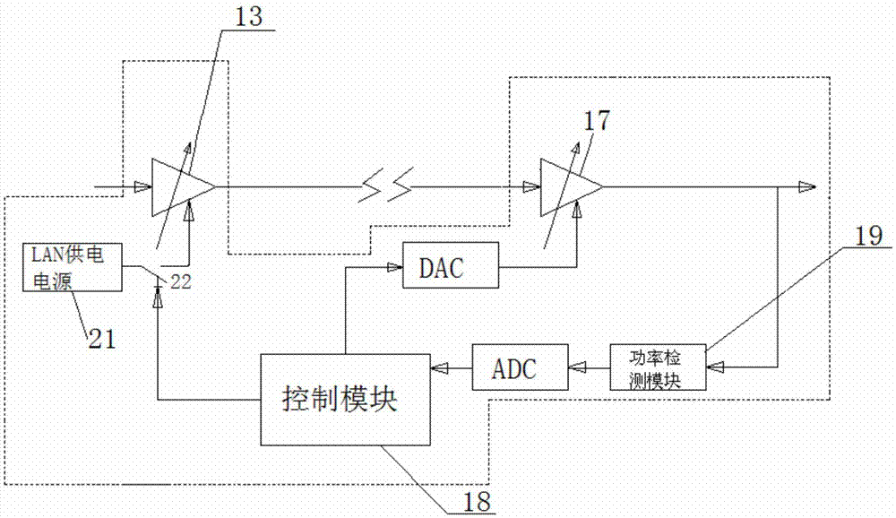
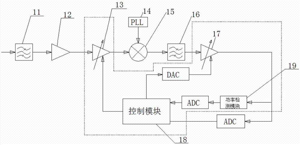
[0029] figure 1 A structural diagram of an AGC device for realizing dynamic range gain according to the first embodiment of the present invention is shown. like figure 1 As shown, the present invention provides an automatic gain control AGC device for realizing dynamic range gain, which may include: a first low noise amplifier LNA 13, used to amplify received electrical signals; AGC module 17, used Amplifying the signal output by the first LNA 13 to output a signal with a stable power level; the power detection module 19 is used to detect the power level of the signal output by the AGC module 17; and The control module 18 is configured to control the first LN...


PUM


Abstract

The invention relates to the field of communication, and discloses an AGC (Automatic Gain Control) device for implementing a dynamic range gain and a radio frequency receiving circuit. The device comprises a first LNA (Low Noise Amplifier), an AGC module, a power detection module and a control module, wherein the first LNA is used for amplifying a received electric signal; the AGC module is used for amplifying a signal output by the first LNA so as to output a signal with a stable power level value; the power detection module is used for detecting the power level value of the signal output by the AGC module; and the control module is used for controlling the first LNA not to amplify a received microwave signal when the power level value of the signal output by the AGC module is greater than a threshold value, so as to further enlarge a dynamic range of a system.

Description

technical field [0001] The present invention relates to the communication field, in particular to an AGC device and a radio frequency receiving circuit for realizing dynamic range gain. Background technique [0002] Electronic Toll Collection (ETC for short) is an intelligent transportation electronic system that realizes automatic toll collection without parking, which is dominated by modern communication technology, electronic technology, automatic control technology, computer and network technology and other high-tech technologies. . Through the dedicated short-range communication between the roadside unit (RSU) and the on-board electronic label (OBU), the system automatically completes the toll collection process without the need for the driver to stop and other toll collectors to operate. [0003] When a vehicle with an on-board tag (OBU) passes through the ETC dedicated channel, it passes from far to near and passes through the roadside unit (RSU). At this time, the O...

Claims


Application Information

Patent Timeline
Patent Type & Authority Applications(China)
IPC IPC(8): H04B1/10H04B1/16
CPCH04B1/16H04B1/109
Inventor 邓海林磊何义生刘洋段磊黄江王志平
Owner AEROSPACE INFORMATION
Learn More