Power supply equipment firm to plug

A technology for power supply and equipment, which is applied to the components, circuits, connections, etc. of connecting devices. It can solve the problems of loose plugging, potential safety hazards, and inability to plug and supply electrical components, so as to achieve stable plugging and prevent electric shock accidents. , Improve the effect of plugging accuracy and plugging speed

Active Publication Date: 2017-07-07
安徽原上草节能环保科技有限公司
View PDF5 Cites 57 Cited by
  • Summary
  • Abstract
  • Description
  • Claims
  • Application Information

AI Technical Summary

Benefits of technology

This patented technology helps keep things secure during use while being inserted or taken out without having them loose easily due to gravity forces. It includes various features like setting up push buttons on the bottom plate of the device's housing, allowing users easy access inside it; arranging rails under the slider bars to ensure smooth movement along their length, ensuring proper alignment before moving back again; providing a mechanism where two parts can automatically lock together if needed, increasing security and reliability over existing systems. Overall, this innovative design enhances the functionality and ease of operation of these devices.

Problems solved by technology

This patented technology describes how current methods for connecting two devices are prone to losing contact due to being pulled or accidentally touched during use. Additionally, manual pullout can cause injury if there's no way to safely remove them from their original position after they have been connected with another device.

Method used


Image

  • Power supply equipment firm to plug
  • Power supply equipment firm to plug
  • Power supply equipment firm to plug

Examples


Embodiment Construction

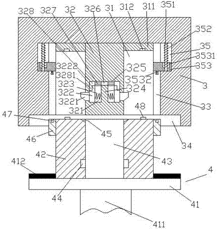
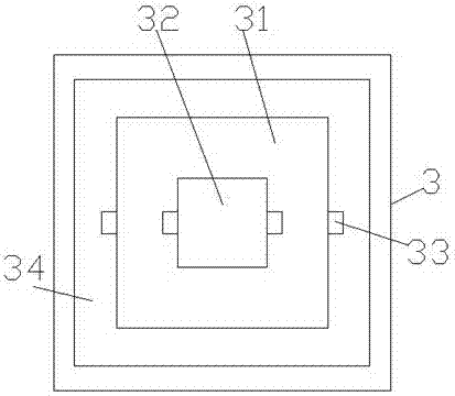
[0019] Such as Figure 1-Figure 6 As shown, a power supply device with strong plugging and plugging in the present invention includes a socket part 3 and a plug part 4 mated with the socket part 3. The socket part 3 is provided with a cavity 31, and the cavity The inner walls of the left and right sides of the chamber 31 are correspondingly provided with a first sliding groove 33, and the top of the first sliding groove 33 is provided with a second sliding groove 35 on the side away from the cavity 31. The slot 35 is provided with a sliding block 353 and a guide rod 351 which is slidingly fitted and connected with the sliding block 353. The inside of the sliding block 353 penetrates into the first sliding groove 33 and is slidingly fitted. The bottom of the sliding block 353 in the first sliding groove 33 is provided with a clamping member 3532, and the inner top wall of the cavity 31 is provided with a downwardly extending insertion rod 32, and the insertion rod 32 The left ...


PUM


Abstract

The invention discloses power supply equipment firm to plug. The power supply equipment comprise a socket part and a plug part, wherein the plug part is plugged into the socket part in a matching way, an accommodating cavity is arranged in the socket part, first sliding grooves are correspondingly formed in inner walls of a left side and a right side of the accommodating cavity, a second sliding groove is formed in one side of the top, deviating from the accommodating cavity, of each first sliding groove, a sliding block and a moving guide rod are arranged in the second sliding groove, the moving guide rod is connected with the sliding block in a sliding and matching way, an inner side of the sliding rod penetrates through the first sliding groove and is matched with the first sliding groove in a sliding way, a clamping piece is arranged at the bottom of the sliding block in the first sliding groove, a plug-in rod is arranged at a top wall in the accommodating cavity and extends downwards, a left hollow cavity and a right hollow cavity are arranged in a lower part of the plug-in rod and are corresponding to each other, baffle blocks are arranged in the hollow cavities in the left side and the right side, a third sliding groove is formed in the top of each hollow cavity, and a push block is arranged in the hollow cavity. The power supply equipment is simple structure and stable in plug and has functions of electric shock prevention and loosening prevention, and the safety and the stability during power supply are improved.

Description


Claims


Application Information

Patent Timeline
Owner 安徽原上草节能环保科技有限公司
Why Eureka
Try Eureka