
Ignition current monitoring circuit for launch control device

A technology of igniting current and monitoring circuit, applied in the direction of measuring current/voltage, measuring only current, circuit device, etc., can solve problems such as result or effect influence, judgment, etc.

Active Publication Date: 2017-07-11
XIAN AEROSPACE PROPULSION TECH INST
View PDF5 Cites 6 Cited by
  • Summary
  • Abstract
  • Description
  • Claims
  • Application Information

AI Technical Summary

Problems solved by technology

That is to say, in this state, when the engine ignition is abnormal, the operator cannot judge the cause of the engine ignition abnormality only by the appearance of the missile and the engine, and can only follow the pre-launch emergency response plan. Press the "launch master command" button again, if it is ignited normally, the missile launch is normal, and continue to perform relevant control actions; if it still does not ignite, then deal with the corresponding emergency situation according to the detonation of the electric squib or non-detonation
Because after the action of "launching the main command", it is an automatic sequence control action. If you cannot make a clear judgment on the abnormal ignition of the engine in time, you can only rely on technical command judgment and emergency plan decision-making to effectively deal with the emergency that occurs. Will have a certain impact on the results or effects of the test task

Method used


Image

  • Ignition current monitoring circuit for launch control device

Examples


Embodiment Construction

[0029] The present invention will be described in detail below with reference to the accompanying drawings and examples.

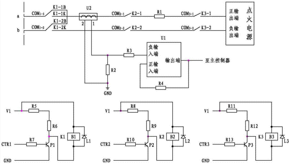
[0030] Such as figure 1 As shown, the ignition current monitoring circuit in this embodiment includes three electromagnetic relays K 1 、K 2 and K 3 , three freewheeling diodes L 1 , L 2 and L 3 , power amplifier U 1 , current sensor U 2 , three transistors P 1 ,P 2 and P 3 , eleven current-limiting resistors R 1 , R 2 , R 3 , R 4 , R 5 , R 6 , R 7 , R 8 , R 9 , R 10 and R 11 .

[0031] For electromagnetic relays, it includes multiple sets of normally open contacts and normally closed contacts, and each common terminal corresponds to a set of normally open contacts and a set of normally closed contacts. Just select the contact and its common terminal.

[0032] Electromagnetic relay K 1 with wire package B 1 , normally open contact K 1-1K , normally closed contact K 1-1B and its corresponding public port COM 1-1 , and the normally...


PUM


Abstract

The invention discloses an ignition current monitoring circuit for a launch control device. The ignition current monitoring circuit is used for monitoring and controlling ignition current output from an ignition power supply of the launch control device, and comprises electromagnetic relays K1 to K3, a power amplifier U1, a current sensor U2, triodes P1 to P3, and current-limiting resistors R1 to R11. The positive output end of the ignition power supply is connected to the point a of the external interface of the control device successively via the K3-1, the COM3-1, the R1, the K2-1, the COM2-1, the K1-1K, and the COM1-1. The negative output end of the ignition power supply is connected to the point b of the external interface of the control device successively via the K3-2, the COM3-2, the K2-2, the COM2-2, the K1-2K, and the COM1-2. The current sensor U2 senses and outputs the ignition current. The point 1 of the current output port of the U2 is connected to the negative input end of the power amplifier U1. The point 2 of the current output port of the U2 is connected to ground. The positive input end of the U1 and the negative output end of the U1 are connected and then are introduced into a main controller. The emitters of the triodes are connected to the ground. The bases of the triodes are connected to a control signal. The collectors of the triodes are connected to V1 through resistors. A solenoid is connected between the V1 and the collectors so that the control signal controls the on-off state of the solenoid.

Description

technical field [0001] The invention belongs to the technical field of ignition control, and in particular relates to a current monitoring circuit, in particular to an ignition current monitoring circuit used for an ignition control device. Background technique [0002] The launch control equipment is a device that completes the pre-launch detection and launch control tasks of the missile. Before the launch, it can conduct a comprehensive functional inspection and status monitoring of each system on the missile and its overall system, and automatically heat and bind the inertial devices on the missile. parameter to put the missile on standby. After receiving the launch command, the launch control equipment controls the battery on the missile to switch to the power supply working state; when all the systems on the missile are working normally, press the "launch master command" button to connect the engine ignition circuit to implement the missile launch . [0003] In the "M...

Claims


Application Information

Patent Timeline
Patent Type & Authority Applications(China)
IPC IPC(8): H02H7/00H02H3/20H02H3/24G01R19/00
CPCG01R19/0092H02H3/207H02H7/00
Inventor 王晓晖龚俊宇纪浩李晖高亢
Owner XIAN AEROSPACE PROPULSION TECH INST
Learn More