Testing device for spring valve vibration frequency response characteristics

A vibration frequency response and testing device technology, applied in the field of hydraulic mechanical systems, can solve problems such as dwell and imperfect spring valve vibration, achieve accurate vibration frequency response characteristics, avoid abnormal vibration failures, and facilitate implementation.

Active Publication Date: 2017-07-14
HARBIN ENG UNIV
View PDF11 Cites 1 Cited by
  • Summary
  • Abstract
  • Description
  • Claims
  • Application Information

AI Technical Summary

Problems solved by technology

So far, most of the tests for spring valves are still in the analysis of the flow field, and the research on the vibration of spring valves is still incomplete.

Method used


Image

  • Testing device for spring valve vibration frequency response characteristics

Examples


Embodiment Construction

[0016] The following is a further detailed description of the test device for the spring valve vibration frequency response characteristic of the present invention in conjunction with the accompanying drawings:

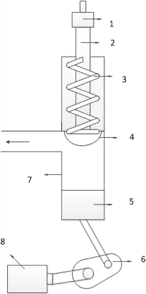
[0017] Such as figure 1 As shown, the present invention provides a testing device for vibration frequency response characteristics of a spring valve, comprising: an acceleration sensor 1, a valve stem 2, a spring 3, a valve core 4, a piston block 5, a crank connecting rod mechanism 6, a valve body 7, Frequency conversion motor 8. Wherein, the acceleration sensor 1 is placed on the extension end of the valve stem 2 , and the extension end of the valve stem 2 protrudes from the valve body 7 ; the valve stem 2 is connected with the spring 3 .

[0018] The piston block 5 is placed on the inner wall of the spring valve body 7, and the lower end of the piston block 5 links to each other with the small end of the crank link mechanism 6; It is used to drive the piston block...


PUM


Abstract

The invention discloses a testing device for spring valve vibration frequency response characteristics. The device comprises an acceleration sensor, a valve rod, a spring, a valve element, a piston block, a crank-link mechanism, a valve body and a variable frequency motor. The acceleration sensor is placed at the extending end of the valve rod, and the extending end of the valve rod extends out of the valve body. The valve rod is connected with the spring. The piston block is arranged on the inner wall of the valve body of a spring valve. The lower end of the piston block is connected with the small end of the crank-link mechanism. The variable frequency motor is connected with the large end of the crank-link mechanism. Pressure pulsed excitation is produced through the variable frequency motor, the vibration acceleration of the spring valve is directly tested through the acceleration sensor, and the device is applicable to testing spring valve vibration frequency response characteristics under various kinds of pressure pulsed excitation.

Description

technical field [0001] The invention is mainly used in hydraulic mechanical systems, and relates to a frequency response characteristic testing device, in particular to a spring valve vibration frequency response testing device. Background technique [0002] The spring valve is one of the key equipment in the various equipment of the hydraulic system, and the stability of its operation has a great impact on the safe operation of the entire hydraulic system. The spring valve is automatically opened and closed according to the working pressure of the pressure system. It is generally installed on the equipment or pipeline of the closed system to protect the safety of the system. When the pressure in the equipment or pipeline exceeds the set pressure of the safety valve, it will automatically open the pressure relief to ensure that the medium pressure in the equipment and pipeline is below the set pressure, protect the normal operation of the equipment and pipeline, prevent acci...

Claims


Application Information

Patent Timeline
Patent Type & Authority Applications(China)
IPC IPC(8): F15B19/00
CPCF15B19/005
Inventor 率志君吕燊黄健哲郭宜斌李凯杰付万葳房楠
Owner HARBIN ENG UNIV
Why Eureka
Try Eureka