Camera calibration method and camera calibration device

A calibration method and camera technology, applied to the device for coating liquid on the surface, computer control, instrument, etc., can solve the problems of reducing the accuracy of dispensing and complicated manual operation

Active Publication Date: 2017-07-14
SHENZHEN ZOWEE TECH
View PDF6 Cites 19 Cited by
  • Summary
  • Abstract
  • Description
  • Claims
  • Application Information

AI Technical Summary

Problems solved by technology

[0003] During the dispensing process, it is usually necessary to manually correct the camera to identify the

Method used


Image

  • Camera calibration method and camera calibration device
  • Camera calibration method and camera calibration device

Examples


Embodiment Construction

[0041] In order to make the object, technical solution and advantages of the present invention clearer, the present invention will be further described in detail below in conjunction with the accompanying drawings and embodiments. It should be understood that the specific embodiments described here are only used to explain the present invention, not to limit the present invention.

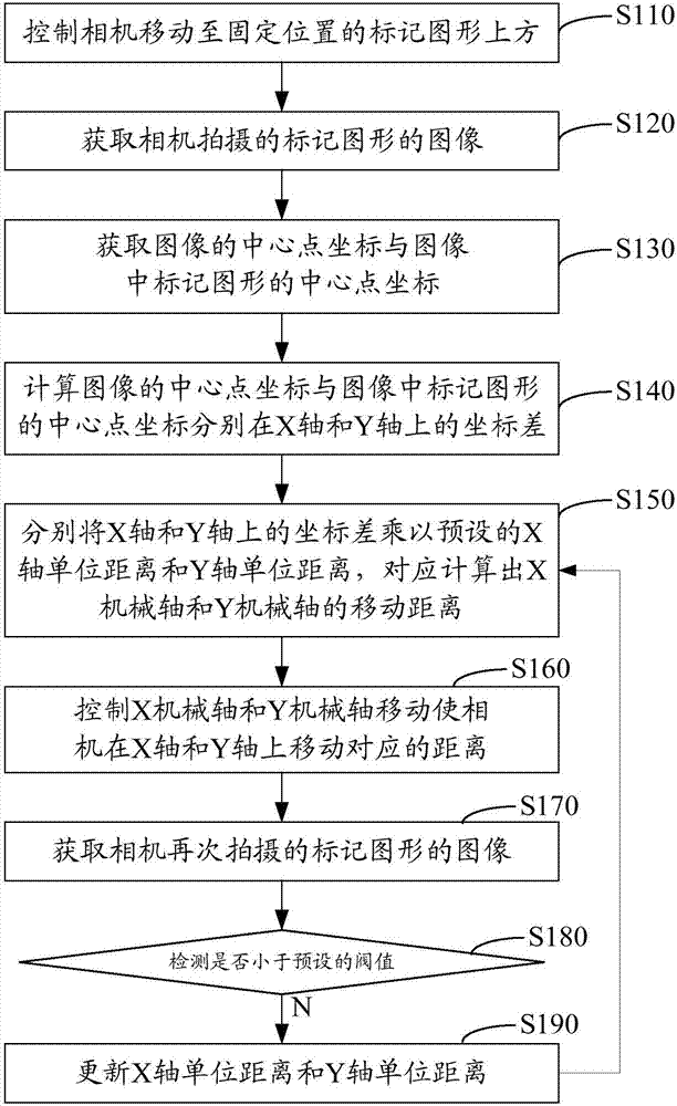
[0042] like figure 1 As shown, the camera calibration method in one embodiment includes steps S110 to S190.

[0043] Step S110 , controlling the camera to move above the fixed-position marker graphic.

[0044] Step S120, acquiring the image of the mark graphic captured by the camera.

[0045] Step S130, acquiring the coordinates of the center point of the image and the coordinates of the center point of the marked figure in the image;

[0046] Step S140, calculating the coordinate difference between the coordinates of the central point of the image and the coordinates of the central point of the...


PUM


Abstract

The invention relates to a camera calibration method and a camera calibration device. The method comprises the following steps: making a camera move to above a graphic mark at a fixed position; acquiring an image of the graphic mark taken by the camera; acquiring the center point coordinates of the image and the graphic mark therein; calculating the coordinate differences between the center point coordinates of the image and the graphic mark therein on the X axis and on the Y axis respectively; multiplying the X-axis and Y-axis coordinate differences by preset X-axis and Y-axis unit distances to get the moving distances of the X and Y mechanical shafts respectively; making the X and Y mechanical shafts move to move the camera corresponding distances on the X axis and on the Y axis respectively; acquiring an image of the graphic mark taken by the camera again; detecting whether the absolute values of the coordinate differences between the center point coordinates of the image taken again and the center point coordinates of the graphic mark in the image are less than a preset threshold; and if the absolute values are less than the preset threshold, updating the X-axis and Y-axis unit distances, and going to the step of calculating the moving distances. Automatic camera calibration is realized, and the accuracy of calibration is improved.

Description

technical field [0001] The invention relates to the technical field of optical communication device processing, in particular to a camera calibration method and device. Background technique [0002] The glue dispenser can accurately point, inject, and drip fluids such as glue and paint to the precise position of each electronic product. Dispensing machines usually include components such as cameras, X and Y mechanical axes, and dispensing nozzles. Among them, the camera needs to be moved to identify the dispensing position on the electronic product, and the movement of the X and Y mechanical axes can make the dispensing nozzle move to the point. Glue position for dispensing. [0003] During the dispensing process, it is usually necessary to manually correct the camera to identify the dispensing position, but the manual operation is more complicated and will reduce the accuracy of dispensing. Contents of the invention [0004] Based on this, it is necessary to provide a c...

Claims


Application Information

Patent Timeline
IPC IPC(8): G05B19/402B05C11/10
Inventor 唐文明
Owner SHENZHEN ZOWEE TECH
Why Eureka
Try Eureka