Trunk roping device and method of use thereof

A tree trunk and rope winding technology, applied in the directions of botanical equipment and methods, application, thin material processing, etc., can solve the problems of the gap between the straw rope and the straw rope, low work efficiency, labor consumption, etc., so as to ensure the winding accuracy and improve the efficiency. , the effect of reducing manpower consumption

Active Publication Date: 2020-04-28
ZHEJIANG COLLEGE OF CONSTR
View PDF6 Cites 0 Cited by
  • Summary
  • Abstract
  • Description
  • Claims
  • Application Information

AI Technical Summary

Problems solved by technology

The existing way of winding straw ropes is hand-held straw ropes. This kind of winding method is inefficient and has large errors. It cannot ensure that the straw ropes are arranged one by one in sequence, and it is easy to cause a gap between the straw ropes.
In the current fast-paced era, manual operation is not only labor-intensive, but also has low work efficiency and low precision

Method used


Image

  • Trunk roping device and method of use thereof
  • Trunk roping device and method of use thereof
  • Trunk roping device and method of use thereof

Examples


Embodiment 1

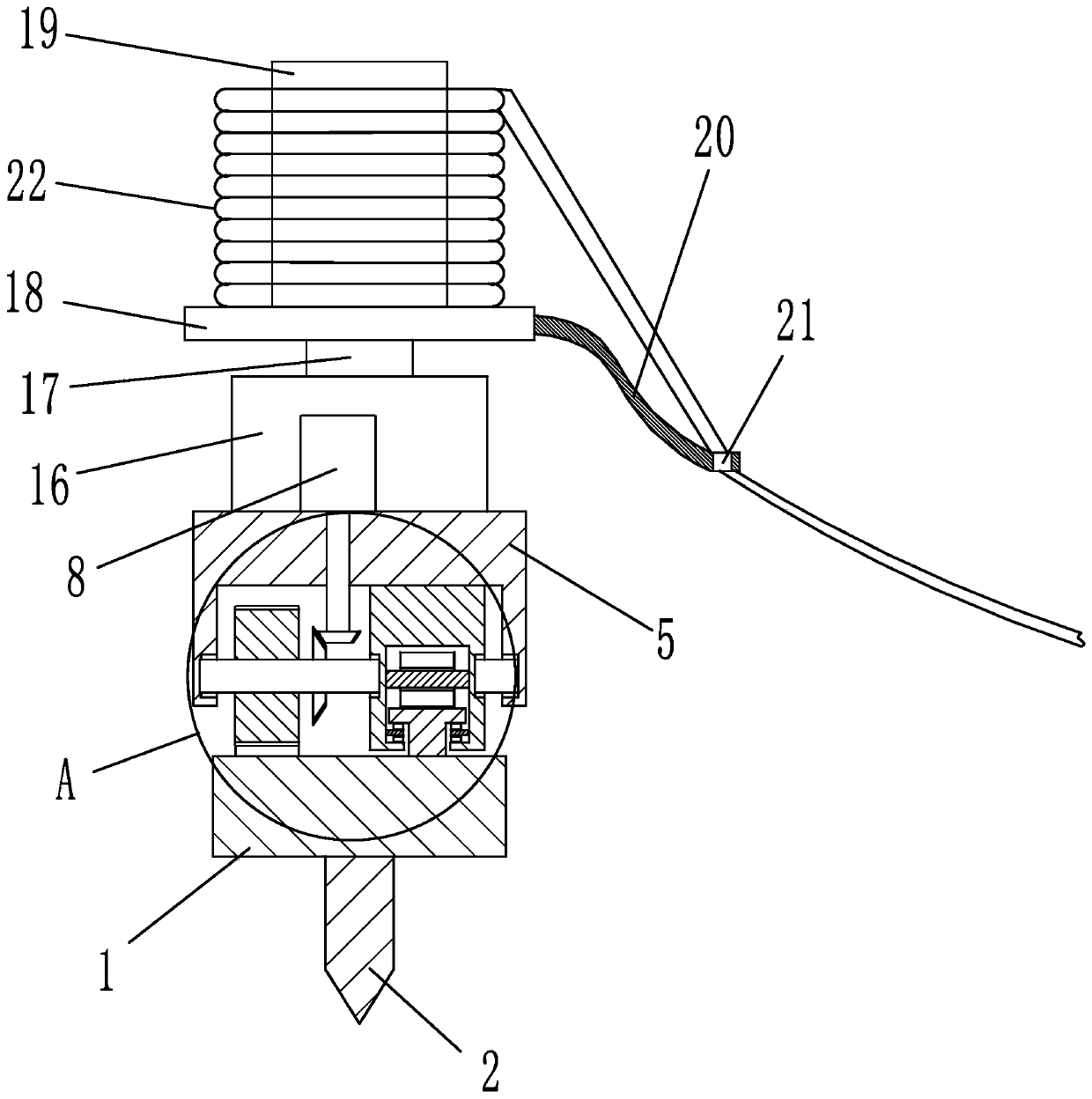
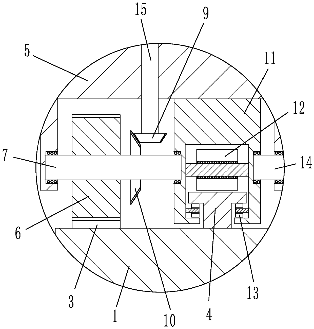
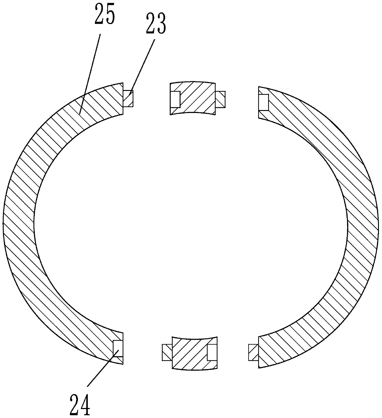
[0024] Embodiment 1: as figure 1 , 2 As shown, a tree trunk roping device includes: a bottom rail 1 for surrounding the trunk, a sliding device capable of moving on the bottom rail, and a lifting device for lifting. The upper end surface of the bottom rail is provided with a feed rack 3 and a limit track 4 equidistant from the feed rack, such as image 3 As shown, the bottom rail includes several arc-shaped splicing sections 25 , one end surface of the splicing section is provided with a positioning plug 23 , and the other end is provided with a positioning slot 24 matched with the positioning plug of another splicing section. The sliding device includes a sliding seat 5, a feed gear 6 meshing with the feed rack, and a sliding limit seat 11 matched with the limit track. The feed gear is rotatably connected to the sliding seat, and the sliding limit seat is fixed to the sliding seat Connected, the upper end surface of the sliding seat is provided with a drive motor 8 for driv...

Embodiment 2

[0027] Embodiment 2: The structure of this embodiment is basically the same as that of Embodiment 1, the difference is that, as Figure 4 , 5 As shown, the end of the sliding limit seat close to the driving shaft is provided with a limit hole 26 matched with the drive shaft, the end of the drive shaft close to the limit hole is provided with a buffer hole 27, and a buffer ball 28 is arranged in the buffer hole, and the buffer ball Fitted with the bottom surface of the limiting hole, a buffer spring 29 with a diameter smaller than the buffer ball is arranged between the buffer ball and the bottom surface of the buffer hole. The driving shaft is located in the limit hole and connected with the wall of the limit hole in rotation. A buffer hole is arranged at the end of the drive shaft close to the limit hole. A buffer ball is arranged in the buffer hole, and a buffer spring is used to push the buffer ball against the limit hole. at the bottom. When the sliding device slides, it...


PUM


Abstract

The invention relates to a trunk protection tool and especially relates to a piece of trunk rope winding equipment and a use method of the same. The trunk rope winding equipment comprises a bottom rail used to surround a trunk, a slide device which can be moved on the bottom rail and a lifting device used for lifting, wherein a feeding rack and a limiting track with the equal spacing of the feeding rack are disposed on the upper end face of the bottom rail; the bottom rail comprises multiple arc spliced sections; and a positioning plug is disposed on the end face of one end of the spliced section and the other end is equipped with a positioning insertion groove which is matched with the positioning plug of another spliced section. The equipment and method provided by the invention have the beneficial effects that manpower consumption can be reduced, working efficiency can be increased, rope winding accuracy of the trunk can be increased, the cost can be reduced, assembly, disassembly and transportation become convenient, etc.

Description

technical field [0001] The invention relates to a tree trunk protection tool, in particular to a tree trunk rope winding device and a use method thereof. Background technique [0002] Usually when surviving the winter, it is necessary to wrap straw ropes on the trunk to protect the trunk. The existing way of winding straw ropes is manual winding with hand-held straw ropes. This winding method is inefficient and has large errors. It cannot ensure that the straw ropes are arranged one by one in sequence, and it is easy to cause gaps between straw ropes. In the current fast-paced era, manual operation is not only labor-intensive, but also has low work efficiency and low precision. Contents of the invention [0003] The present invention mainly aims at the above-mentioned problems, and provides a tree trunk rope winding device and its use method which can reduce manpower consumption, improve work efficiency, improve tree trunk rope winding precision, reduce cost, and facilita...

Claims


Application Information

Patent Timeline
Patent Type & Authority Patents(China)
IPC IPC(8): B65H54/02
CPCA01G13/0237
Inventor 孔杨勇
Owner ZHEJIANG COLLEGE OF CONSTR
Why Eureka
Try Eureka