New energy automobile charging pile device

A technology of new energy vehicles and charging piles, applied in electric vehicle charging technology, charging stations, electric vehicles, etc., can solve the problems of damaged charging line insulation, people trampled on, vehicles crushed, and the service life of charging lines is reduced, achieving improved Improve work efficiency, reduce manual collection of charging lines, and prevent accidental electric shocks

Inactive Publication Date: 2017-07-21
湖南远成能源科技股份有限公司
View PDF7 Cites 17 Cited by
  • Summary
  • Abstract
  • Description
  • Claims
  • Application Information

AI Technical Summary

Problems solved by technology

[0003] The charging pile is an important part of the electric vehicle charging / swapping station. The standard charging pile comes with a charging cable and a charging gun. The charging cable has a certain length. Since the current charging pile does not have the function of automatically winding the charging cable, if Throw the charging cable on the ground at will, so that the charging cable is vulnerable to various unexpected stresses, such as people stepping on it, rolling over by a car, etc., which will cause the outer insulation of the charging cable to be damaged, resulting in a decrease in the life of the charging cable; Safety voltage, once the insulation is damaged, there will be safety hazards such as abnormal insulation, if it is not found in time, it will cause accidents such as electric shock

Method used


Image

  • New energy automobile charging pile device
  • New energy automobile charging pile device
  • New energy automobile charging pile device

Examples


Embodiment Construction

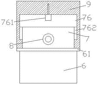
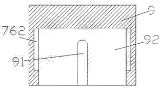
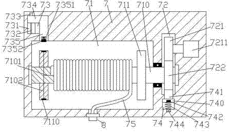
[0025] Such as Figure 1-Figure 8 As shown, a new energy vehicle charging pile device of the present invention includes a support column 6, a body 7 fixed on the top of the support column 6, and a lifting protective cover 9 arranged outside the top of the body 7. The body 7 A first cavity 71 is provided inside, a second cavity 72 is provided in the body 7 on the right side of the first cavity 71, and a second cavity 72 is provided in the body 7 above the left side of the first cavity 71. The first sliding cavity 73, the body 7 below the second cavity 72 is provided with a second sliding cavity 74, the first cavity 71 is provided with a rotating shaft 710 extending to the left and right sides, so The extension section on the right side of the rotating shaft 710 runs through the inner wall of the body 7 and extends into the second cavity 72 and is connected in a rotational fit. The rotating shaft 710 in the first cavity 71 is symmetrically provided with stops plate 711, the rot...


PUM


Abstract

The invention discloses a new energy automobile charging pile device. The new energy automobile charging pile device comprises a supporting column, a machine body fixed to the top of the supporting column, and a lifting protection cover arranged on the outer side of the top of the machine body. A first cavity is formed in the machine body. A second cavity is arranged in the part, on the right side of the first cavity, in the machine body. A first sliding cavity is formed in the part, above the left side of the first cavity, in the machine body. A second sliding cavity is formed in the part, below the second cavity, in the machine body. A rotary shaft extending left and right is arranged in the first cavity. The right side of the rotary shaft penetrates through the inner wall of the machine body, extends into the second cavity, and is in rotational fit connection with the second cavity. Baffles are symmetrically arranged on the part, in the first cavity, of the rotary shaft left and right. A charging cable is arranged on the part, between the baffles, of the rotary shaft in a wound mode. A first guide line is arranged in the left side of the rotary shaft. The tail end of the left side of the charging line is embedded into the rotary shaft and electrically connected with the first guide line. Conductive ring plates are arranged outside the left baffle in a wound mode. The new energy automobile charging pile device is simple in structure, convenient to operate and capable of automatically winding the charging line, meanwhile, the safety is improved, and electric shock accidents are prevented.

Description

technical field [0001] The invention relates to the technical field of new energy vehicles, in particular to a charging pile device for new energy vehicles. Background technique [0002] Electric vehicles refer to vehicles powered by vehicle-mounted power supplies, driven by motors to drive wheels, and meeting the requirements of road traffic and safety regulations. Compared with gasoline engine vehicles, electric vehicles have less impact on the environment and can replace the use of non-renewable energy gasoline. Therefore, the prospect of electric vehicles is widely optimistic, and it also meets the requirements of new energy strategies. [0003] The charging pile is an important part of the electric vehicle charging / swapping station. The standard charging pile comes with a charging cable and a charging gun. The charging cable has a certain length. Since the current charging pile does not have the function of automatically winding the charging cable, if Throw the chargin...

Claims


Application Information

Patent Timeline
Patent Type & Authority Applications(China)
IPC IPC(8): B60L11/18
CPCB60L53/30B60L53/31Y02T10/70Y02T10/7072Y02T90/12
Inventor 戚祖盛
Owner 湖南远成能源科技股份有限公司
Why Eureka
Try Eureka