Electric welding device

A welding device and electric welding machine technology, which is applied to welding accessories and other directions, can solve the problems of power supply line damage, inconvenient power supply line retraction, induced electric shock, etc., to prevent electric shock accidents, reduce manual cable collection, and improve work efficiency.

Inactive Publication Date: 2018-07-03
邵潘英
View PDF0 Cites 0 Cited by
  • Summary
  • Abstract
  • Description
  • Claims
  • Application Information

AI Technical Summary

Problems solved by technology

[0002] At present, electric welding machines are more and more widely used. However, due to the relatively short power supply line of electric welding machines, it often affects the movement of electric welding machines during welding. In the past, when encountering similar phenomena, one or more wires are generally used. The board is lengthened and connected to achieve the purpose of plugging and powering the electric welding machine. However, after multiple terminal boards are connected, the power supply line has a certain length, which is extremely inconvenient when retracting, and the power supply line is thrown on the ground at will during the power supply process, so the power supply line It is easy to be damaged by various accidents, such as people stepping on it, scratching by hard objects, etc., which will cause damage to the outer insulation of the power supply line, resulting in a decrease in the life of the power supply line; Accidental touch may induce electric shock, and there is a great potential safety hazard

Method used


Image

  • Electric welding device
  • Electric welding device
  • Electric welding device

Examples


Embodiment Construction

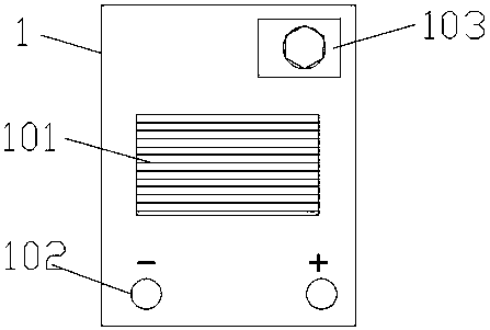
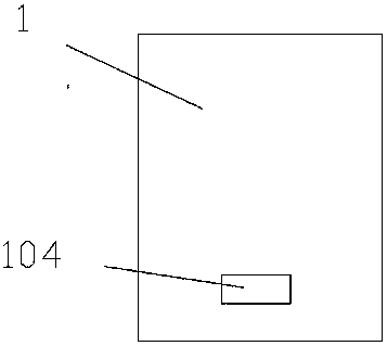
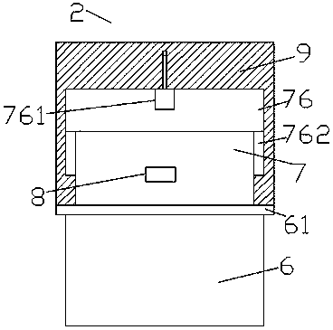
[0025] Such as Figure 1-Figure 9 As shown, an electric welding device of the present invention includes an electric welding machine 1 and a connecting piece 2, and the connecting piece 2 consists of a vertical pole 6, a container 7 fixed on the top of the vertical pole 6, and a 7 top outer casing 9 is combined, a first cavity 71 is provided in the container 7, a second cavity 72 is provided in the container 7 on the right side of the first cavity 71, the The first sliding cavity 73 is provided in the container 7 above the left side of the first cavity 71, and the second sliding cavity 74 is provided in the container 7 below the second cavity 72. The cavity 71 is provided with a rotating shaft 710 extending to the left and right sides. The extended section on the right side of the rotating shaft 710 penetrates the inner wall of the container 7 and penetrates into the second cavity 72 and is connected in operation. The rotating shaft 710 in the first cavity 71 is provided with...


PUM


Abstract

The invention discloses an electric welding device. The electric welding device comprises an electric welding machine and a connecting part; the connecting part is composed of a stand rod, a containing box fixed to the top of the stand rod and a shell sleeve arranged on the outer side of the top of the containing box, a first containing cavity is formed in the containing box, a second containing cavity is formed in the portion, on the right side of the first containing cavity, of the containing box, a first sliding cavity is formed in the portion, over the left side of the first containing cavity, and a second sliding cavity is formed in the portion, under the second containing cavity, of the containing box; and a rotating shaft stretching towards the left side and the right side is arranged in the first containing cavity, the right-side stretching section of the rotating shaft penetrates through the inner wall of the containing box, penetrates into the second containing cavity, runs and is connected with the second containing cavity in a matched mode, stopping columns are symmetrically arranged on the portion, in the first containing cavity, of the rotating shaft left and right, acable is arranged on the portion, between the stopping columns, of the rotating shaft in a winding mode, a first wire is arranged in the left side of the rotating shaft, the left-side tip of the cable is embedded into the rotating shaft and electrically connected with the first wire, and a guiding ring is arranged on the exterior of the left stopping column in a winding mode. According to the electric welding device, the structure is simple, operation is convenient, the cable can be automatically wound, the safety is improved, and accidental electric shock accidents are prevented.

Description

technical field [0001] The invention relates to the field of welding technology, in particular to an electric welding device. Background technique [0002] At present, electric welding machines are used more and more widely. However, due to the relatively short power supply line of electric welding machines, it often affects the movement of electric welding machines during welding. In the past, one or more wires are usually used to encounter similar phenomena. The board is lengthened and connected to achieve the purpose of plugging and powering the electric welding machine. However, after multiple terminal boards are connected, the power supply line has a certain length, which is extremely inconvenient when retracting, and the power supply line is thrown on the ground at will during the power supply process, so that the power supply line It is easy to be damaged by various accidents, such as trampling by people, scratching by hard objects, etc., which will cause damage to th...

Claims


Application Information

Patent Timeline
Patent Type & Authority Applications(China)
IPC IPC(8): B23K9/32
CPCB23K9/32
Inventor 邵潘英
Owner 邵潘英
Why Eureka
Try Eureka