Capacitor discharging tool

A capacitor and tool technology, applied in the direction of circuits, electrical components, conductive connections, etc., can solve the problem that the discharge tool cannot meet the discharge requirements, and achieve the effect of changing the direction of the discharge operation.

Pending Publication Date: 2017-07-21
STATE GRID JIANGSU ELECTRIC POWER CO LTD MAINTENANCE BRANCH +1
View PDF7 Cites 2 Cited by
  • Summary
  • Abstract
  • Description
  • Claims
  • Application Information

AI Technical Summary

Problems solved by technology

For capacitors, in addition to single-stage discharge to ground, two-stage phase-to-phase discharge is also required (see Figure 4 Shown is the structure schematic diagram of the existing single capacitor), the early discharge tools can not meet the discharge requirements

Method used


Image

  • Capacitor discharging tool
  • Capacitor discharging tool
  • Capacitor discharging tool

Examples


Embodiment 1

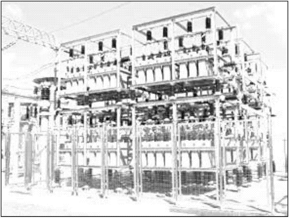
[0041] Embodiment 1, intensive capacitor discharge application: after entering the capacitor bank, perform touch discharge operations on various equipment around you in sequence. For dense capacitors, an insulating sheath will generally be added to the pile head of the casing in the later stage to prevent short-circuit faults between phases of small animals. Just discharge it.

Embodiment 2

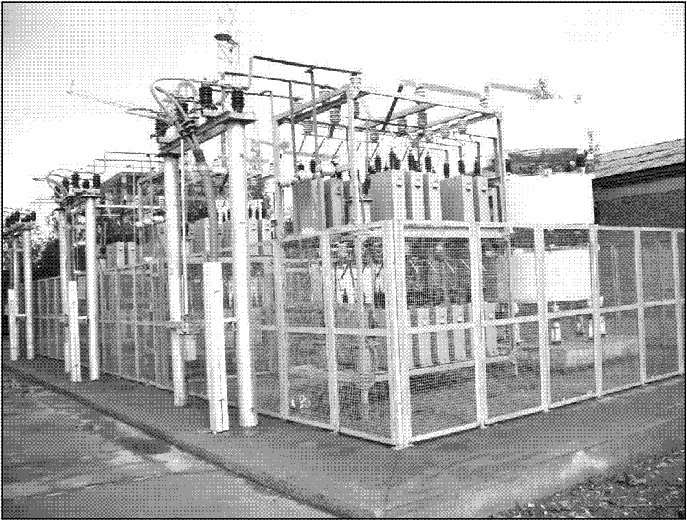
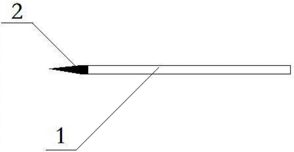
[0042] Embodiment 2, the discharge application of the frame type capacitor bank: only the hook-like part 7 of the present invention hooks one of the first stages of the capacitor lightly, and gently pushes along the trend, and under the action of the spring, the metal grounding rod 3 and the insulating operating rod 2 An angle is formed between them to ensure that the entire metal grounding rod 3 is in contact with the two stages of the capacitor to meet the requirements of single-stage and phase-to-phase discharge of the capacitor, and to discharge multiple times one by one according to the regulations. Figure 8 It is a schematic diagram of the use state of the elastic connector of the present invention when the bend is less than 90 degrees. In the figure, A is the use state of the elastic connector when it is bent at 0 degrees, and B is the elastic connector when the bend is greater than 0 degrees and less than The use state at 90 degrees, Figure 9 It is a schematic diagra...

Embodiment 3

[0043] Embodiment 3, the application of the discharge at the central point of the capacitor bank: there is no phase-to-phase discharge in the discharge at the central point, and you only need to hold the present invention in your hand and operate it at any position.

[0044] The present invention designs and installs a spring between the metal grounding rod 3 and the insulating operating rod 2, through the bending angle and recoverability of the spring, it can meet the operation requirements that the operator can easily discharge when standing at any position, and can simultaneously Ground and phase-to-phase discharge operation.


PUM


Abstract

The invention discloses a capacitor discharging tool, which comprises an insulated operation bar, a metal grounding bar, an elastic connector, a connection wire and a grounding wire, wherein the insulated operation bar is connected with the metal grounding bar through the elastic connector; two ends of the elastic connector are fixedly connected with the top end of the insulated operation bar and the bottom end of the metal grounding bar respectively; the top end of the connection wire is fixedly arranged at the bottom end of the metal grounding bar; the bottom end of the connection wire and the top end of the grounding wire are fixedly arranged on the insulated operation bar; the bottom end of the connection wire is fixedly connected with the top end of the grounding wire; the bottom end of the grounding wire is provided with a grounding end wire clamp for grounding; the top end of the metal grounding bar is provided with a linear extending sharp part and a bent extending hook part; and one end of the sharp part is fixedly connected with one end of the hook part. The traditional discharging mode is broken, the spring device is additionally arranged between the discharging metal part and the insulation rod, and through the bent angle and the recoverability of the spring, the discharging operation direction is changed, and the operation is more humanized.

Description

technical field [0001] The invention relates to a capacitor discharge tool, which belongs to the technical field of capacitor discharge. Background technique [0002] The capacitor bank works in a power failure. Although the discharge PT and the grounding knife can release most of the charge, there will still be residual charge on the capacitor at that time, especially after the fuse of the capacitor is broken, a large amount of charge will remain on the capacitor. If you do not discharge , Electric shock will occur; electric power safety regulations stipulate that before entering the capacitor bank to work, the capacitors must be discharged several times one by one. [0003] At present, there is no special discharge tool at the work site. Generally, the ground wire of the substation is used for discharge, and additional procedures for borrowing and returning the ground wire need to be performed; capacitor banks in the substation are generally arranged on 2 to 3 floors (see ...

Claims


Application Information

Patent Timeline
Patent Type & Authority Applications(China)
IPC IPC(8): H01R4/66H01R11/01
CPCH01R4/66H01R11/01
Inventor 张磊仇文艺赵小军陈轩
Owner STATE GRID JIANGSU ELECTRIC POWER CO LTD MAINTENANCE BRANCH
Why Eureka
Try Eureka