
Soil pushing device special for spiral

A technology of soil scraper and screw, applied in the field of screw special soil scraper, can solve problems such as waste of power resources, waste of resources, delay of time, etc., and achieve the effect of reducing waste of human resources, improving work efficiency and long service life

Inactive Publication Date: 2013-06-19
LUOYANG SHUCHENG MACHINERY EQUIP
View PDF5 Cites 6 Cited by
  • Summary
  • Abstract
  • Description
  • Claims
  • Application Information

AI Technical Summary

Problems solved by technology

[0002] At present, during the use of the known long screw pile driver at the construction site, the soil, mud, stones and other sundries drilled out of the drill pipe from the ground during the piling process adhere to the drill pipe. Its own weight causes a waste of resources for lifting power
The sundries stuck to the drill pipe are lifted tens of meters high together with the drill pipe, and the sundries lifted tens of meters high pose a safety hazard to the workers working below
It is often necessary to wear a safety helmet to clean up the sundries on the drill pipe during construction on the construction site. Because the lifting speed is relatively fast, the sundries cannot be cleaned cleanly, and even the cleaning tool is involved in the drill pipe, resulting in damage to the cleaning tool and personal injury
Moreover, during the piling process, a large amount of excreted muck is produced, and a large amount of muck is excreted and accumulated around the drill pipe, which hinders the next construction. The next step of construction can only be carried out after cleaning, which delays time and wastes resources

Method used


Image

  • Soil pushing device special for spiral
  • Soil pushing device special for spiral
  • Soil pushing device special for spiral

Examples


Embodiment Construction

[0032] The present invention will be further described below in conjunction with the accompanying drawings and embodiments, but this does not constitute any limitation to the present invention.

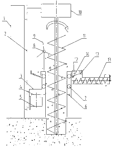
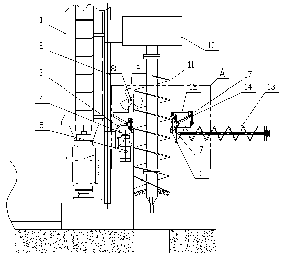
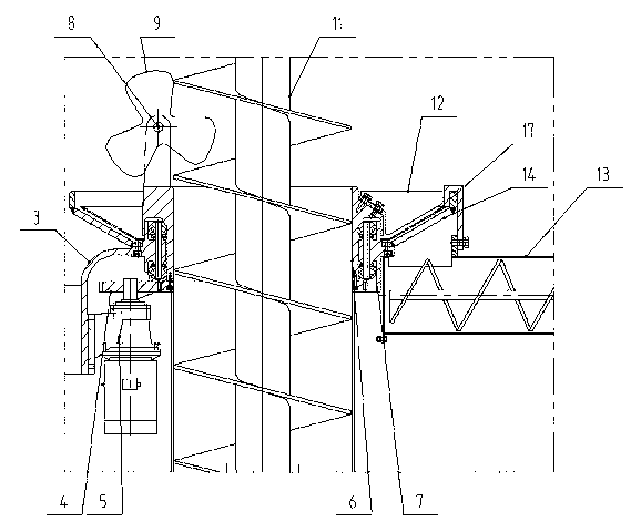
[0033] Such as figure 1 , figure 2 shown, and refer to image 3 , a screw special soil mover, the body 3 of the soil mover is located on the guide rail 2 of the pile driver frame; the reducer II 10 drives the drill pipe 11 to rotate forward, reverse and move up and down; the soil mover has a rotary body 6, which rotates The driving element of the body 6 is a motor (not shown in the figure) and is provided with a reducer I5, and the reducer I5 is located on the body 3 of the earth mover; a gear pair is formed by the teeth on the input gear 4 and the rotary body 6, and the motor 1. The speed reducer I5 rotates the rotary body 6 through the teeth on the input gear 4 and the rotary body 6. The center of the rotary body of the rotary body is located on the axis of the drill rod of the p...


PUM


Abstract

The invention relates to a supporting facility of a pile hammer, in particular to a soil pushing device for spiral. A device body (3) of the soil pushing device is arranged on a rack (1) of the pile hammer. The soil pushing device is provided with a revolved body (6). A revolved center of a circle of the revolved body (6) is located on an axis of a drill stem of the pile hammer to form a structure that the revolved body (6) rotates around the drill stem (11) of the pile hammer. The revolved body (6) of the soil pushing device is provided with a drive element and a driving element. The revolved body is provided with a soil pushing element. The soil pushing element is an impeller (9) or an elastic body. The soil pushing device for the spiral can achieve effects of soil pushing and soil conveying when the drill stem moves in an up and down mode without rotating, the drill stem rotates without moving in an up and down mode, the drill stem rotates and moves in an up and down mode, and the drill stem rotates forwards or rotates backwards. The soil pushing device for the spiral can remove sundries such as soil, mud, stones and the like on a drill stem spiral, workers who are under construction under the ground have no potential safety hazard, and working efficiency is improved.

Description

technical field [0001] The present invention relates to supporting facilities of pile drivers, in particular to a special screw earth mover, which is used in conjunction with pile drivers to remove and transport sundries on the helical blades of drill rods of the pile drivers. Background technique [0002] At present, during the use of the known long screw pile driver at the construction site, the soil, mud, stones and other sundries drilled out of the drill pipe from the ground during the piling process adhere to the drill pipe. Its own weight causes a waste of resources for lifting power. The sundries stuck to the drill pipe are lifted tens of meters high together with the drill pipe, and the sundries lifted tens of meters high pose a safety hazard to the workers working below. It is often necessary to wear a safety helmet to clean up the sundries on the drill pipe during construction on the construction site. Because the lifting speed is relatively fast, the sundries can...

Claims


Application Information

Patent Timeline
Patent Type & Authority Applications(China)
IPC IPC(8): E21B12/06
Inventor 胡其金
Owner LUOYANG SHUCHENG MACHINERY EQUIP
Learn More