
An optical fiber terminal box placement frame

A technology of terminal boxes and racks, which is applied in the field of optical fibers, can solve the problems of pulling and breaking optical fiber lines, and easy movement, etc., and achieves the effects of convenient fixing and clamping, preventing movement, and simple structure

Active Publication Date: 2019-11-19
HEBEI YANG DAY COMM TECH
View PDF5 Cites 0 Cited by
  • Summary
  • Abstract
  • Description
  • Claims
  • Application Information

AI Technical Summary

Problems solved by technology

[0002] In this information age, optical fiber networks have spread all over people's living quarters and around their residences. Generally, before using the network, optical fiber cables must be connected to terminal boxes. Traditional terminal boxes are placed directly on the ground indoors, which is prone to Move, which will cause pulling on the fiber optic cable, or even break the fiber optic cable

Method used


Image

  • An optical fiber terminal box placement frame
  • An optical fiber terminal box placement frame

Examples


Embodiment Construction

[0015] The following will clearly and completely describe the technical solutions in the embodiments of the present invention with reference to the accompanying drawings in the embodiments of the present invention. Obviously, the described embodiments are only some, not all, embodiments of the present invention.

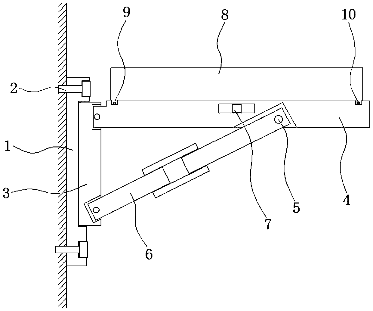
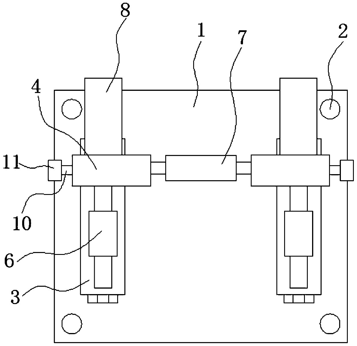
[0016] refer to Figure 1-2 , an optical fiber terminal box placement rack, including a fixed plate 1, the four corners of the fixed plate 1 are screwed with locking screws 2, the fixed plate 1 is fixedly connected to the wall through four locking screws 2, and the fixed plate 1 is far away from the wall One side of the body is symmetrically provided with two installation grooves, the inner side wall of the installation groove is connected with the connection block 3 through the rotation of the first rotating shaft, and the side of the connection block 3 away from the inner bottom of the installation groove penetrates the notch of the installation groove and extends o...


PUM


Abstract

The invention discloses a fiber terminal box rack, comprising a fixing plate; a lock screw is threadedly connected to each corner of the fixing plate, the fixing plates is fixedly connected to a wall through the four lock screws, one side of the fixing plate far away from the wall is symmetrically provided with two mounting grooves, a connection block is rotationally connected to the inner wall of each mounting groove through a first rotary shaft, one side of each connection block far away from the inner bottom of the corresponding mounting groove is extended out through an opening of the corresponding mounting groove, the extension side of each connection block is rotationally connected with a horizontally arranged support rod, the lower side of each support rods is provided with a connection groove, a first turnbuckle is rotationally connected to the inner wall of each connection groove through a second rotary shaft, and one end of each first turnbuckle far away from one end of the corresponding second rotary shaft is rotationally connected to the corresponding connection block. The fiber terminal box rack is simple in structure and convenient to use, and allows a fiber terminal box to be fixed and clamped conveniently to prevent movement of the fiber terminal box which causes breakage of fibers.

Description

technical field [0001] The invention relates to the field of optical fiber technology, in particular to an optical fiber terminal box placement frame. Background technique [0002] In this information age, optical fiber networks have spread all over people's living quarters and around their residences. Generally, before using the network, optical fiber cables must be connected to terminal boxes. Traditional terminal boxes are placed directly on the ground indoors, which is prone to Move, which will cause pulling on the fiber optic cable, or even break the fiber optic cable. In order to solve the above problems, we propose a shelf for optical fiber terminal boxes. Contents of the invention [0003] The purpose of the present invention is to solve the shortcomings in the prior art, and propose an optical fiber terminal box placement frame. [0004] In order to achieve the above object, the present invention adopts the following technical solutions: [0005] An optical fib...

Claims


Application Information

Patent Timeline
Patent Type & Authority Patents(China)
IPC IPC(8): G02B6/44
CPCG02B6/4446
Inventor 林建宝
Owner HEBEI YANG DAY COMM TECH
Learn More