
Mechanical coded lock

A technology of mechanical coded locks and bolts, applied in the field of mechanical coded locks, can solve the problems of easy cracking of coded locks and low reliability, and achieve the effect of increasing the difficulty of cracking and high reliability

Active Publication Date: 2017-08-01
深圳市万厦福智能锁业有限公司
View PDF11 Cites 3 Cited by
  • Summary
  • Abstract
  • Description
  • Claims
  • Application Information

AI Technical Summary

Problems solved by technology

[0003] The purpose of the present invention is to provide a mechanical combination lock to solve the problems that the existing combination locks are easy to crack and have low reliability

Method used


Image

  • Mechanical coded lock
  • Mechanical coded lock
  • Mechanical coded lock

Examples


Embodiment Construction

[0032] In order to further explain the technical means and effects of the present invention to achieve the intended purpose of the invention, the specific implementation, structure, features and effects of the present invention will be described in detail below in conjunction with the accompanying drawings and examples.

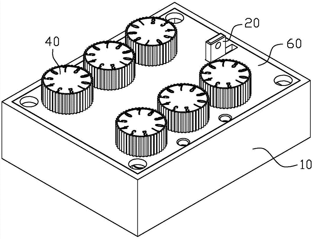
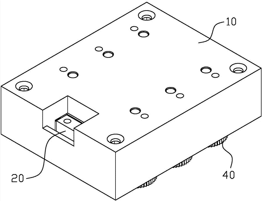
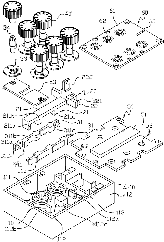
[0033] figure 1 It is a schematic diagram of the overall structure of the mechanical combination lock in the first embodiment of the present invention, figure 2 for figure 1 Schematic diagram of the structure from another angle, image 3 for figure 1 Schematic diagram of the split structure in . Please refer to Figure 1 to Figure 3 , a kind of mechanical password lock provided by the present invention comprises:

[0034] The base 10 includes a base plate 11 and a side plate 12. The base plate 11 is provided with a support seat 111 and a plurality of barrier blocks 112 arranged at intervals in an inline shape, and the two barrier blocks 112 at the front...


PUM


Abstract

The invention discloses a mechanical coded lock which comprises a base, a spring bolt, and a locking mechanism. The base comprises a bottom plate and a side plate, wherein the bottom plate is provided with multiple stop blocks which are arranged at intervals in a linear shape. The spring bolt comprises a spring bolt body part and a spring bolt control part arranged at one end of the spring bolt body part. Multiple supporting feet are arranged at the bottom of the spring bolt body part, each supporting foot is correspondingly arranged between the corresponding two adjacent stop blocks, and a control rod is arranged on the spring bolt control part. The locking mechanism comprises a lock piece assembly, lock bars and elastic pieces. The lock piece assembly comprises a lock piece and a lock piece rotating shaft in transition fit with the lock piece, wherein multiple locking concave openings and one unlocking concave opening are formed in the circumference of the lock piece. One side of each lock bar comprises multiple limiting blocks which are arranged at intervals and lock bar limiting pillars located at the two ends of the lock bar. The elastic pieces are correspondingly arranged on the lock bar limiting pillars in a sleeving manner. The other side face of each lock bar is provided with protrusions, wherein the number of the protrusions is the same with the number of the corresponding limiting blocks, and each limiting block is located between the corresponding supporting foot and the corresponding stop block.

Description

technical field [0001] The invention relates to the technical field of locks, and in particular to a mechanical combination lock. Background technique [0002] At present, domestic existing combination locks are generally divided into three categories: mechanical combination locks, electronic combination locks and electromechanical combination locks. Mechanical combination lock has a long history, and its characteristics are: easy to use and low price. Its disadvantages are: the number of passwords is not enough, once the passwords are manufactured, they cannot be changed, and the mechanical passwords are easy to be cracked. With people's higher requirements on the performance of anti-theft locks and the development of digital technology, a new type of electronic combination lock controlled by a microprocessor has been widely used in recent years. Press the key to enter the password, it is easy and convenient to open, there are many passwords, and it is easy to change the ...

Claims


Application Information

Patent Timeline
Patent Type & Authority Applications(China)
IPC IPC(8): E05B37/20E05B15/10E05B15/00E05B15/16
CPCE05B15/00E05B15/10E05B15/1614E05B37/20
Inventor 方永秋程来胜
Owner 深圳市万厦福智能锁业有限公司
Learn More