High-energy optical fiber cutter

A cutting knife and optical fiber technology, applied in the direction of optical waveguide coupling, etc., can solve the problems of increasing optical fiber detection cost and reducing production efficiency, and achieve the effect of reducing production cost and improving production efficiency

Inactive Publication Date: 2017-08-01
SHANDONG PACIF OPTICS FIBER & CABLE CO LTD
View PDF0 Cites 0 Cited by
  • Summary
  • Abstract
  • Description
  • Claims
  • Application Information

AI Technical Summary

Problems solved by technology

[0002] The fiber cleaver is one of the indispensable devices when performing optical fiber cross-section detection. The existing fiber cleaver can only be used in conjunction with the corresponding fiber detector, and the corresponding fiber detector has to be replaced when the fiber detector is replaced. Optical fiber cleaver, which increases the cost of optical fiber inspection and reduces production efficiency

Method used


Image

  • High-energy optical fiber cutter

Examples


Embodiment Construction

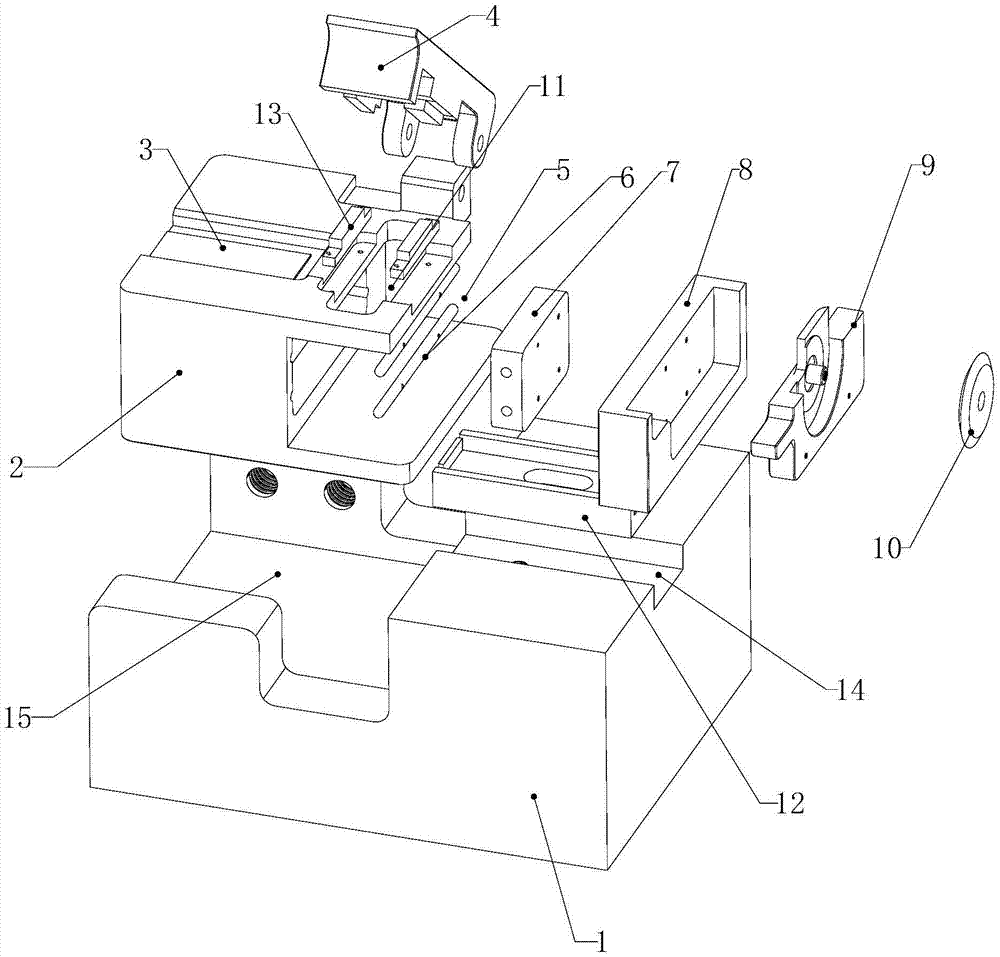
[0013] The specific implementation manners of the present invention will be further described in detail below in conjunction with the accompanying drawings and embodiments. The following examples are used to illustrate the present invention, but are not intended to limit the scope of the present invention.

[0014] see figure 1 , a high-energy fiber optic cutter in a preferred embodiment of the present invention, comprising a base 1, a base 2 is fixedly arranged on the base, an optical fiber guide groove 3 is arranged on the base, and a cover plate 4 is hingedly arranged on one side of the base , the base below the cover plate is provided with a cutting groove 5, a cutting device is arranged in the cutting groove, the cutting device includes a slider guide rail 6 and a slider 7 arranged on the slider guide rail, and a knife holder seat is fixedly arranged on the slider 8. A knife rest 9 is arranged on the knife rest seat, and a cutting knife 10 is rotatably arranged on the kn...


PUM


Abstract

The invention relates to a high-generality high-energy optical fiber cutter capable of being matched with various different types of optical fiber detectors for use. The high-generality high-energy optical fiber cutter comprises a bottom seat; a base is fixedly arranged on the bottom seat; an optical fiber guide groove is arranged in the base; one side of the base is hinged with a cover plate; the base below the cover plate is internally provided with a cutting groove; a cutting device is arranged in the cutting groove; the cutting device comprises a guide rail and a sliding block arranged on the guide rail; a cutter holder seat is fixedly arranged on the sliding block; a cutter holder is arranged on the cutter holder seat; the cutter is arranged on the cutter holder in a rotatable mode; the upper surface of the base is provided with a cutting hole; the upper part of the cutter is located in the cutting hole; the upper surface of the bottom seat is also provided with an optical fiber clamp guide rail along the optical fiber guide groove direction; and the optical fiber clamp guide rail is used for setting an optical fiber clamp.

Description

technical field [0001] The invention relates to an optical fiber production device, in particular to a high-energy optical fiber cutter. Background technique [0002] The fiber cleaver is one of the indispensable devices when performing optical fiber cross-section detection. The existing fiber cleaver can only be used in conjunction with the corresponding fiber detector, and the corresponding fiber detector has to be replaced when the fiber detector is replaced. Optical fiber cleaver, thereby increasing the cost of optical fiber detection and reducing production efficiency. [0003] In view of the above-mentioned defects, the designers are actively researching and innovating in order to create a new type of optical fiber cleaver to make it more industrially useful. Contents of the invention [0004] In order to solve the above technical problems, the object of the present invention is to provide a versatile high-energy fiber optic cutter that can be used in conjunction wi...

Claims


Application Information

Patent Timeline
Patent Type & Authority Applications(China)
IPC IPC(8): G02B6/25
CPCG02B6/25
Inventor 陈怀勇孟昭立李广省
Owner SHANDONG PACIF OPTICS FIBER & CABLE CO LTD
Why Eureka
Try Eureka