An optical measuring bench device

An optical measurement and bench technology, which is applied in the direction of measuring devices, optical instrument testing, and testing optical performance, can solve the problems of unsuitable commercial testing equipment and achieve the effects of improved interchangeability, simple operation, and open device structure

Active Publication Date: 2019-07-09
INST OF MICROELECTRONICS CHINESE ACAD OF SCI
View PDF5 Cites 0 Cited by
  • Summary
  • Abstract
  • Description
  • Claims
  • Application Information

AI Technical Summary

Problems solved by technology

Moreover, different measurement experiments sometimes require dismantling the optical system, replacing optical components and detecting sensors, so commercial test equipment is not suitable for such applications

Method used


Image

  • An optical measuring bench device
  • An optical measuring bench device
  • An optical measuring bench device

Examples


Embodiment Construction

[0044] Exemplary embodiments of the present disclosure will be described in more detail below with reference to the accompanying drawings. Although exemplary embodiments of the present disclosure are shown in the drawings, it should be understood that the present disclosure may be embodied in various forms and should not be limited by the embodiments set forth herein. Rather, these embodiments are provided for more thorough understanding of the present disclosure and to fully convey the scope of the present disclosure to those skilled in the art.

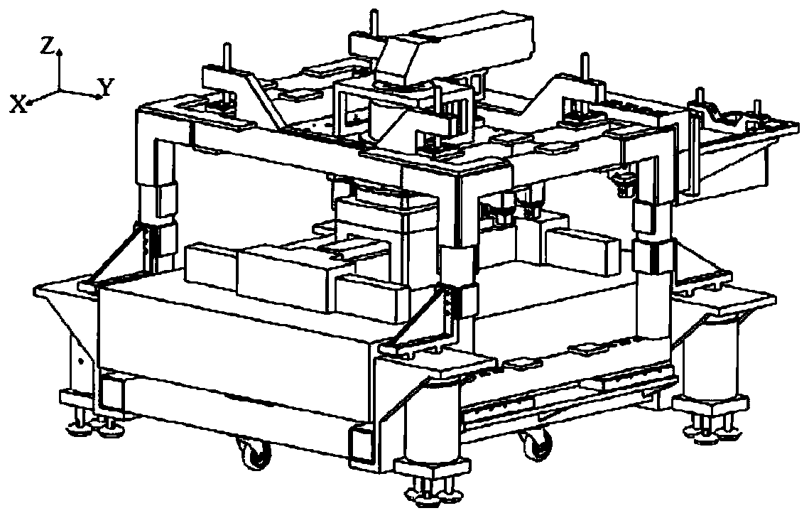
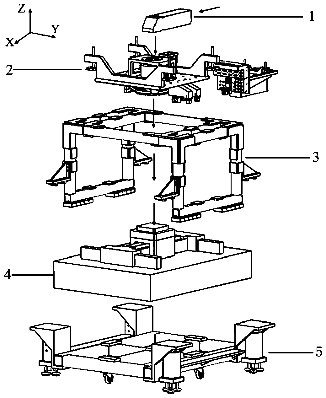
[0045] The present invention proposes an optical measuring bench device, such as figure 1 As shown, it shows the overall structure diagram of the measuring bench device according to the embodiment of the present invention. Depend on figure 2 It can be seen from the exploded view that the platform structure consists of five parts from top to bottom: the uppermost layer is a uniform lighting system 1, which is used to introduce lig...


PUM


Abstract

The invention relates to an optical measuring stand apparatus. A stand structure comprises an uniform illumination system, a panel support structure, a lower layer support framework, a displacement bench and a movable air floating pedestal from top to bottom. By using the stand apparatus, a problem that structures of detection systems of a Shark-Hartmann sensor, a double-grating shearing interference and the like are difficult to adjust is solved. An adjusting stroke of a certain range is possessed and lens groups with different focal lengths are compatible. A center of the stand apparatus is provided with a large installing hole. Through an adapter flange, lens with different diameters are compatible. And design layout is open, which is convenient for dismounting and integration installation.

Description

technical field [0001] The invention belongs to the technical fields of detection of optical element / system performance parameters, detection of light source performance parameters, etc., and specifically relates to the detection of optical performance parameters of a lens system and the detection of performance parameters of an accompanying detection light source, and is particularly suitable for detection of performance parameters of lens groups. Background technique [0002] The more traditional optical measurement method is to use optical components with mechanical structures, and the results are obtained by visual observation by testers. There are large errors in data observation, data analysis, and calculation processes. Due to the rapid development of computer technology in recent years, as well as the great progress of semiconductor photoelectric conversion sensors and image acquisition devices such as CCD and CMOS. Optical measurement has entered a stage based on im...

Claims


Application Information

Patent Timeline
Patent Type & Authority Patents(China)
IPC IPC(8): G01M11/02
CPCG01M11/0271
Inventor 齐威齐月静王宇卢增雄
Owner INST OF MICROELECTRONICS CHINESE ACAD OF SCI
Why Eureka
Try Eureka