Battery state detection method

A battery status and detection method technology, applied to the detection of faulty computer hardware, electrical digital data processing, instruments, etc., can solve the problems of occupying CPU time slices, reducing execution efficiency, time slice idling, etc., achieving high integration, The effect of reducing interaction and improving efficiency

Active Publication Date: 2015-01-28
THE 41ST INST OF CHINA ELECTRONICS TECH GRP
View PDF3 Cites 2 Cited by
  • Summary
  • Abstract
  • Description
  • Claims
  • Application Information

AI Technical Summary

Problems solved by technology

[0012] (1) In the traditional process, if the state parameters of the battery are read through the SMBUS control core, when the CPU generates the specified data according to the SMBUS protocol, the software needs to perform the following operations. Under normal circumstances, the CPU needs to perform each step of operation. Interact with the battery status chip once, so that after completing a reading and writing process, the CPU interacts with the SMBUS control core multiple times, and the CPU performs a write operation, waiting for the battery status chip to return a response signal. After the response signal, enter the next step. One-step operation, during the waiting process, will occupy CPU resources, causing time slices to idle, reducing execution efficiency
[0013] (2) In the traditional way, the CPU is a high-speed device, while the SMBUS is a slow device. The SMBUS control core is realized by software programming. When processing in an interrupt mode, it adopts a polling working method, which occupies CPU time slices, and its efficiency is low.
[0014] (3) In the traditional way, the CPU is a high-speed device, while the SMBUS is a slow device. Using software programming to realize the SMBUS control core has low efficiency

Method used


Image

  • Battery state detection method
  • Battery state detection method
  • Battery state detection method

Examples


Embodiment Construction

[0064] The following will clearly and completely describe the technical solutions in the embodiments of the present invention with reference to the accompanying drawings in the embodiments of the present invention. Obviously, the described embodiments are only some, not all, embodiments of the present invention. Based on the embodiments of the present invention, all other embodiments obtained by persons of ordinary skill in the art without making creative efforts belong to the protection scope of the present invention.

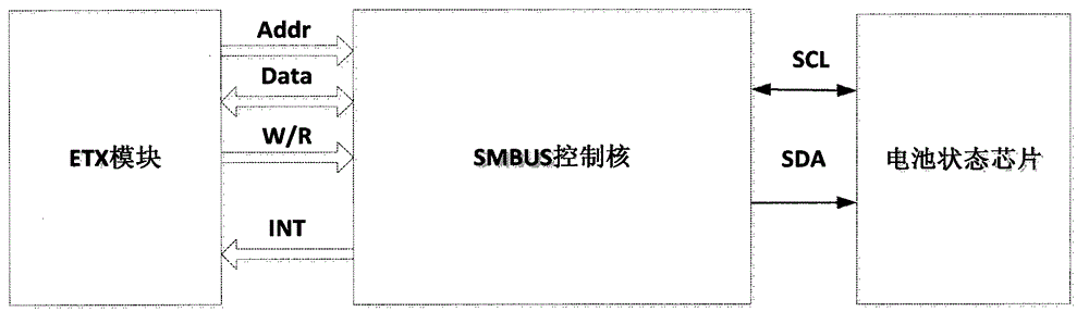
[0065] In the existing battery state detection method, each time an operation is performed, the host computer needs to interact with the battery status chip once. After completing a reading and writing process, the host computer and the SMBUS control core perform multiple interactions, and the host computer performs a write operation. Wait for the battery status chip to return a response signal. After the response signal, enter the next step of operation. Durin...


PUM


Abstract

The invention provides a battery state detection method based on a system. The system comprises a host machine, an SMBUS control core and a battery state chip, wherein the SMBUS control core is in charge of interaction of the host machine and the battery state chip; the host machine only interacts with the battery state chip once; the interaction state is controlled by virtue of the SMBUS control core; a read operation and a write operation are realized in the SMBUS control core; handshaking of each operation step is executed in a state machine of the SMBUS control core; the SMBUS control core comprises seven registers which are respectively a PRERLo clock low-order register, a PRERHi clock high-order register, a CTR control register, a TXR transmission register, an RXR receiving register, a CR (Command Register) and an SR (State Register). The battery state detection method is capable of improving the transmission speed as much as possible so as to eliminate idling of a time slice of the host machine.

Description

technical field [0001] The invention relates to the technical field of electronic measurement, in particular to a battery state detection method. Background technique [0002] In the field of electronic measurement, hand-held measurement and bench-top measuring instruments have batteries, and SMBUS bus is used to read the battery status for the battery status. Under normal circumstances, when reading a battery parameter, the CPU needs to interact with the battery multiple times, causing the CPU time slice to idle, and the transmission efficiency is low. At the same time, the traditional state machine is used, and the state is redundant. [0003] The SMBUS (Smart Manegement Bus) bus is the interconnection interface between the host, smart battery charger, smart selector, smart battery and peripherals in the SBS (Smart Battery System) of the smart battery system. The SMBUS bus is a standard bus structure between the components of the smart battery system. It is developed on t...

Claims


Application Information

Patent Timeline
Patent Type & Authority Applications(China)
IPC IPC(8): G06F11/22G06F13/38
Inventor 李伟白轶荣张士峰辛义磊朱伟
Owner THE 41ST INST OF CHINA ELECTRONICS TECH GRP
Why Eureka
Try Eureka