Common mode choke coil

A common-mode choke coil, first-line technology, applied in the direction of transformer/inductor coil/winding/connection, inductor, fixed transformer or mutual inductance, etc., can solve the problems of mode conversion characteristics reduction, easy inconsistency, etc., to achieve mode Effects with good transformation characteristics

Active Publication Date: 2017-08-11
MURATA MFG CO LTD
View PDF7 Cites 7 Cited by
  • Summary
  • Abstract
  • Description
  • Claims
  • Application Information

AI Technical Summary

Problems solved by technology

[0026] In addition, when the chip-type common mode choke coil 31 is mounted on a mounting board, it is soldered via the terminal electrodes 41 to 44, but the shape of the solder applied to each electrode of the terminal electrodes 41 to 44 is affected by the influence of the terminal electrodes 41 to 44. Influenced by the shape, the shape of the conductive solder ring on the mounting substrate side, etc., it is easy to be inconsistent and can bring asymmetry
[0027] As described above, if asymmetry is brought about in the wound wire structure or in parts other than the wound wire structure, asymmetry or directivity also occurs in electrical characteristics such as inductance and capacitance. As a result, the mode conversion characteristics cannot be reduced as theoretically

Method used


Image

  • Common mode choke coil
  • Common mode choke coil
  • Common mode choke coil

Examples


Embodiment Construction

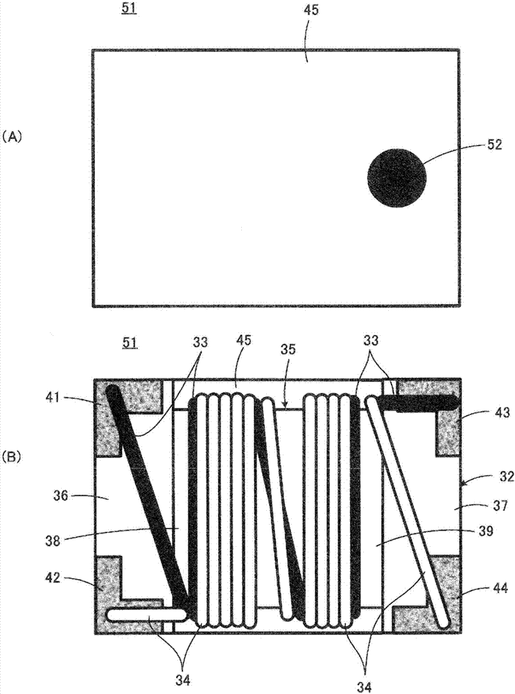
[0060] figure 1 A common mode choke coil 51 according to the first embodiment of the present invention is shown. with the above Figure 11 shown in the common mode choke coil 31 compared to the figure 1 The illustrated common mode choke coil 51 is substantially the same except for the winding method of the first wire 33 and the second wire 34 . Thus, in figure 1 in, right with Figure 11 Components corresponding to the shown components are denoted by the same reference numerals, and overlapping explanations are omitted.

[0061] exist figure 1 In , in order to clearly distinguish the first line 33 and the second line 34, the first line 33 is schematically shown in black, and the second line 34 is schematically shown in hollow.

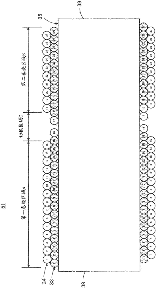
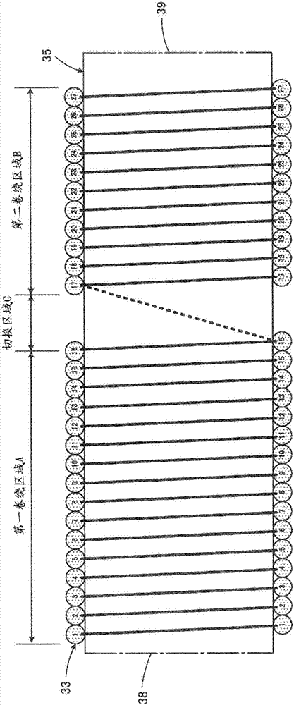
[0062] exist figure 2 shown in schematic cross-section figure 1 The winding state of the first wire 33 and the second wire 34 in the common mode choke coil 51 is shown. Compared figure 1 (B) and figure 2 , about the number of turns of ...


PUM


Abstract

A common mode choke coil includes a core having a winding core part and a first and second wire wound around the winding core part. The winding core part has a first winding region, a switching region and second winding regions in this order along the axis of the winding core part. In the first winding region, each turn of the first wire is located closer to a first end portion of the winding core part than the corresponding same-numbered turn of the second wire. In the second winding region, each turn of the first wire is located closer to a second end portion of the winding core part than the corresponding same-numbered turn of the second wire. The number of turns of the first and second wires in the first winding region differs from the number of turns of the first and second wires in the second winding region.

Description

technical field [0001] The present invention relates to a common mode choke coil, and more particularly to a wound wire type common mode choke coil having a structure in which two wires are wound around a winding core having both ends. Background technique [0002] refer to Figure 11 and Figure 12 The general structure of the common mode choke coil 31 which becomes the object of this invention is demonstrated. [0003] Such as Figure 11 As shown, the common mode choke coil 31 is provided with the magnetic core 32, and the 1st wire 33 and the 2nd wire 34 which respectively comprise an inductor. The magnetic core 32 is made of an electrically insulating material, more specifically, aluminum as a dielectric, Ni—Zn-based ferrite as a magnetic body, or resin or the like. The magnetic core 32 has a rectangular cross section as a whole. The wires 33 and 34 are made of, for example, copper wires covered with insulation. [0004] The magnetic core 32 has a winding core portion...

Claims


Application Information

Patent Timeline
Patent Type & Authority Applications(China)
IPC IPC(8): H01F27/24H01F27/28H01F27/29H01F27/30
CPCH01F27/24H01F27/28H01F27/2823H01F27/29H01F27/306H01F17/03H01F17/045H01F19/04H01F27/2828H01F27/292H01F2017/0093
Inventor 宫本昌史山本滋人山口健太郎
Owner MURATA MFG CO LTD
Why Eureka
Try Eureka