Microswitch

A technology of micro-switches and moving contacts, applied in the direction of electric switches, contacts, electrical components, etc., can solve the problems of volume limitation, difficulty in assembling micro-switches, the number of auxiliary switches cannot meet the requirements, etc., and achieve the current-carrying area The effect of large and large opening distance

Inactive Publication Date: 2017-08-18
江苏高博锐电气有限公司
View PDF4 Cites 0 Cited by
  • Summary
  • Abstract
  • Description
  • Claims
  • Application Information

AI Technical Summary

Problems solved by technology

[0004] In electrical equipment and power distribution appliances, with the development of various precision instruments and equipment and grid communications, various indication functions, communication functions, and interlocking functions require more auxiliary switches. The original one-on-one-off auxiliary switch The quantity can no longer meet the requirements, and the volume of many devices has been limited. It is difficult to assemble more micro switches without increasing the volume.

Method used


Image

  • Microswitch
  • Microswitch
  • Microswitch

Examples


Embodiment Construction

[0022] The present invention will be described in detail below in conjunction with the drawings and specific implementations:

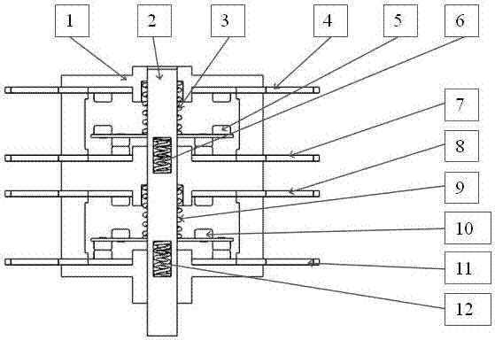
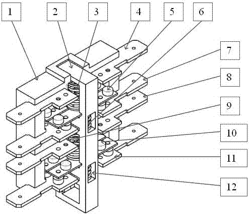
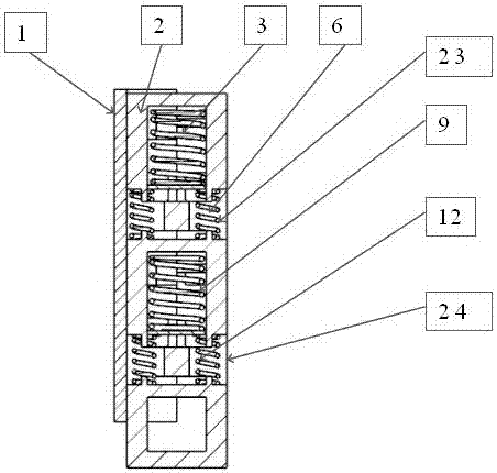
[0023] Such as Figure 1 to Figure 8 The micro switch shown includes a housing 1 and a slider 2, and a first static contact 4, a second static contact 7, and a third static contact fixedly mounted on the housing 1 from top to bottom. The head 8, the fourth static contact 11, further includes a first moving contact 5 and a second moving contact 10. The contact points of the first static contact 4 and the third static contact 8 are set downwards, so The contact points of the second static contact 7 and the fourth static contact 11 are arranged upward, and the contact points on the upper and lower sides of the first moving contact 5 correspond to the first static contact 4 and the second static contact respectively. The contact points of the contact 7 are set, and the contact points on the upper and lower sides of the second movable contact 10 correspond t...


PUM


Abstract

The invention discloses a microswitch, and the microswitch comprises a housing and a sliding block. The sliding block is slidingly disposed in an internal chute of the housing. The interior of a first spring groove is provided with a first spring, and the interior of a second spring groove is provided with a second spring. The interior of a third spring groove is provided with a third spring, and the third spring is partly exposed in the first spring groove. The interior of a fourth spring groove is provided with a fourth spring. The fourth spring is partly exposed in the second spring groove. A first movable contact is installed between the first spring and the second spring, and a second contact is installed between the second spring and the fourth spring. The stiffness factors of the third and fourth springs are respectively greater than the stiffness factors of the first and second springs. The microswitch is provided with two normally-opened and normally-closed contacts. Because the upper and lower normally-opened and normally-closed contacts independently complete the conversion, the opening distance is large and the movable and static contact current-carrying area is large, there are no problems of false connection, small capacity and poor connection and disconnection capability in the conversion process.

Description

[0001] Technical field: [0002] The invention belongs to the technical field of low-voltage power distribution equipment, and particularly relates to a micro switch of a circuit breaker. [0003] Background technique: [0004] In electrical equipment and power distribution appliances, with the development of various precision instruments and power grid communications, various indication functions, communication functions, and interlocking functions require more auxiliary switches. The original auxiliary switches are open and closed. The quantity has not been able to meet the requirements, and the volume of many devices has been limited. It is difficult to assemble more micro switches without increasing the volume. [0005] Summary of the invention: [0006] The technical problem to be solved by the present invention is to provide a two-open and two-close micro switch with small volume and low cost. [0007] In order to solve the above technical problems, the present invention is realize...

Claims


Application Information

Patent Timeline
IPC IPC(8): H01H13/64
CPCH01H13/64H01H1/2025
Inventor 刘言菊邓高见李大意朱金星段新高
Owner 江苏高博锐电气有限公司
Why Eureka
Try Eureka