Movable static contact structure of small current moulded case circuit breaker with current limiting device

A technology of molded case circuit breakers and dynamic and static contacts, which is applied in the direction of circuit breaker contacts and circuit breaker components, etc., can solve the problems of small current molded case circuit breakers such as current limiting, so as to improve utilization rate, reduce burning loss, reduce The effect of production costs

Active Publication Date: 2015-02-11
EATON HUINENG LOW-VOLTAGE ELECTRICAL (JIANGSU) CO LTD
View PDF5 Cites 0 Cited by
  • Summary
  • Abstract
  • Description
  • Claims
  • Application Information

AI Technical Summary

Problems solved by technology

[0005] In order to solve the current limiting problem of the existing small current plastic case circuit breaker, the present invention proposes a small current plastic case circuit breaker contact structure with a current limiting device, which can not only enhance the magnetic field in the static contact area but also increase the small current plastic contact structure. The loop resistance of the case circuit breaker realizes the loop current limitation

Method used


Image

  • Movable static contact structure of small current moulded case circuit breaker with current limiting device
  • Movable static contact structure of small current moulded case circuit breaker with current limiting device
  • Movable static contact structure of small current moulded case circuit breaker with current limiting device

Examples


Embodiment Construction

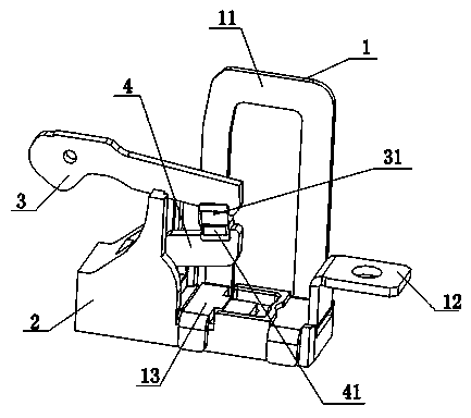
[0026] Such as figure 2 As shown, the present invention consists of a movable static contact bracket 2 , a current limiting device 1 , a movable contact 3 and a movable static contact 4 . The movable and static contact bracket 2 is fixedly connected to the movable and static contact 4 and the current limiting device 1, the movable contact 3 is located on the upper part of the movable and static contact 4, the movable contact 31 on the movable contact 3 and the static contact on the static contact 4 The contacts 41 are disconnected and contacted with each other to realize current switching.

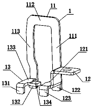
[0027] Such as Figure 2-3 As shown, the current limiting device 1 is composed of continuous first, second and third parts, or may be composed of the first, second and third parts connected in sequence. The first part 12 is on the far right and is the incoming line end part. The third part 13 is located on the left side of the first part, and the third part 13 is connected with the mov...


PUM


Abstract

The invention discloses a movable static contact structure of a small current moulded case circuit breaker with a current limiting device. A current limiting device comprises three parts which are continuous or are sequentially connected. The first part is a wire inlet end on the rightmost side; the third part is connected with a movable static contact and positioned under the movable static contact; the second part is an inverse U-shaped structure comprising a first bent surface, a second bent surface and a third bent surface which are continuous; the first bent surface and the second bent surface respectively in bridge joint with the front side or back side between the first part and the third part; and the second bent surface is always higher than a movable contact. A static contact point on the static contact and a movable contact point on the movable contact are positioned in the left and right symmetrical center of the first bent surface and the third bent surface. While the magnetic field of a contact area is enhanced, the return circuit resistance of the whole circuit breaker can also be increased, the current-limiting performance of the circuit breaker is improved, and the movable contact and static contact can be guaranteed to be more rapidly repelled apart.

Description

technical field [0001] The invention relates to a low-current molded case circuit breaker in the field of low-voltage electrical technology, in particular to a static contact structure of the small-current molded case circuit breaker, and belongs to the field of low-voltage electrical technology. Background technique [0002] At present, according to the nature of the load and the protection function required by the load, small current molded case circuit breakers with a rated current below 32A are still widely used. In order to achieve its breaking index, reduce the actual current when breaking, and protect the internal components from being burned, the traditional small current molded case circuit breaker generally adopts the method of increasing the internal circuit resistance to achieve the purpose of current limiting. In order to increase the current limiting resistance and achieve the purpose of current limiting, the conductive circuit parts of the circuit breaker are ...

Claims


Application Information

Patent Timeline
Patent Type & Authority Patents(China)
IPC IPC(8): H01H73/04
Inventor 胡义琴陈咸李冰燕
Owner EATON HUINENG LOW-VOLTAGE ELECTRICAL (JIANGSU) CO LTD
Why Eureka
Try Eureka