automatic transfer switch

An automatic transfer switch, micro switch technology, applied in the direction of electric switches, power devices, circuits inside the switch, etc., can solve the problems of small rotation angle of the moving contact shaft, limited breaking capacity, limited arc extinguishing performance, etc., to improve the Breaking index, large rotation angle, and the effect of being conducive to arc extinguishing

Active Publication Date: 2020-11-20
SHENZHEN TAIYONG ELECTRICAL TECH
View PDF3 Cites 0 Cited by
  • Summary
  • Abstract
  • Description
  • Claims
  • Application Information

AI Technical Summary

Problems solved by technology

However, due to the limitation of the structure of the switching operation device, the rotation angle of the moving contact shaft is small (usually within 60 degrees), so that the opening distance between the moving and static contacts is small, which limits the improvement of its arc extinguishing performance. The improvement of breaking capacity is also limited

Method used


Image

  • automatic transfer switch
  • automatic transfer switch
  • automatic transfer switch

Examples


Embodiment Construction

[0037] In order to have a clearer understanding of the technical features, purposes and effects of the present invention, the specific implementation manners of the present invention will now be described in detail with reference to the accompanying drawings.

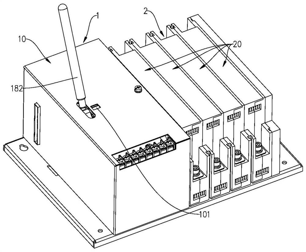
[0038] Such as figure 1 As shown, the automatic transfer switching apparatus in some embodiments of the present invention includes a transfer operation device 1 and a main circuit device 2 . The main circuit device 2 may comprise at least one monopole assembly 20 arranged side by side. The switching operation device 1 can be arranged on one side of the main circuit device 2 and connected in linkage with the main circuit device 2 to provide driving force for the main circuit device 2 and realize the opening and closing function of the main circuit device 2 .

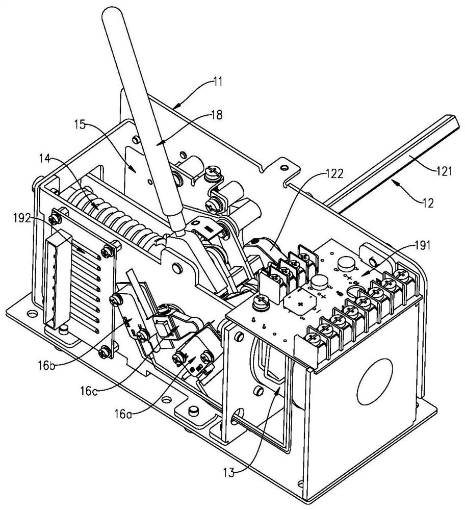
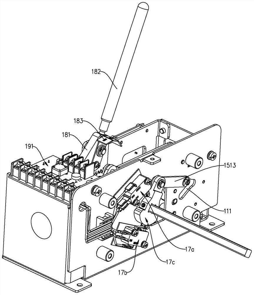
[0039] Such as Figure 2-9 As shown, the switching operation device 1 may include a bracket assembly 11 , a rotating shaft assembly 12 installed on the bracket a...


PUM


Abstract

The invention relates to an automatic change-over switching apparatus, which comprises a main circuit device and a change-over operation device. The change-over operation device includes a support assembly, an electromagnet assembly and an elastic energy storage assembly mounted on the support assembly, and a rotating shaft assembly connected with the electromagnet assembly and the elastic energystorage assembly. The rotating shaft assembly includes a rotating shaft rotationally mounted on the support assembly and an eccentric wheel mounted on the rotating shaft. The rotating shaft extends out of the support assembly and is connected with a moving contact assembly of the main circuit device to drive the moving contact assembly to rotate. When the electromagnet assembly is powered on, therotating shaft assembly is driven to rotate to storage energy for the elastic energy storage assembly. After the electromagnet assembly is powered off, the eccentric wheel drives the rotating shaft tocontinue to rotate in the same direction by using the inertia thereof under the combined action of the elastic energy storage assembly. Therefore, large-rotation-angle movement of the rotating shaftassembly is realized, the opening distance of the connected moving contact assembly is increased, and the breaking index can be improved.

Description

technical field [0001] The invention relates to the field of low-voltage electrical appliances, and more specifically relates to an automatic transfer switch electrical appliance. Background technique [0002] The transfer switch appliance is a common low-voltage electrical appliance, which is often used in important power distribution occasions (such as hospital power supply systems) to switch between two power supplies. When the common power supply fails during the power supply process, it will quickly switch to the backup power supply to ensure load normal power supply at the terminal. [0003] At present, in the contact structure of the existing two-stage automatic transfer switch electrical appliances, the movable contact is usually movable and the static contact is fixed. When the automatic transfer switch is switching the power supply, it mainly realizes the power switching by driving the moving contact to rotate through the action of the switching operation device. ...

Claims


Application Information

Patent Timeline
Patent Type & Authority Patents(China)
IPC IPC(8): H01H3/30
CPCH01H3/3005
Inventor 黄正乾朱熔吾曾宏
Owner SHENZHEN TAIYONG ELECTRICAL TECH
Why Eureka
Try Eureka