Parison cold cutting and sealing device of blow molding machine

A blow molding machine and cutting knife technology, which is applied in the field of parison cold cutting and encapsulation devices, can solve the adverse effects on the safety of inspection operators, inspection efficiency and even inspection quality, the limitation of the degree of repulsion, and the inability to meet the requirements of repulsion. and other problems to achieve the effect of improving inspection efficiency, ensuring safety, and improving inspection quality.

Pending Publication Date: 2018-11-06
SUZHOU TONGDA MACHINERY
View PDF2 Cites 0 Cited by
  • Summary
  • Abstract
  • Description
  • Claims
  • Application Information

AI Technical Summary

Problems solved by technology

In the aforementioned process, since the two cutter frames are fixed with very sharp cutters (that is, blades) in the opposite state, and because it is subjectively desired that the distance between the two cutter frames be The larger the space, the safer it is to prevent the cutter from cutting the operator's limbs such as the arm. However, because the gear box cannot move, the degree of repulsion between the two cutter holders and the cutter is limited, that is, the desired repulsion requirements cannot be met.
Therefore, it will have adverse effects on the safety of inspection operators, inspection efficiency and even inspection quality.

Method used


Image

  • Parison cold cutting and sealing device of blow molding machine
  • Parison cold cutting and sealing device of blow molding machine
  • Parison cold cutting and sealing device of blow molding machine

Examples


Embodiment Construction

[0023] In order to understand the technical essence and beneficial effects of the present invention more clearly, the applicant will describe in detail the following examples, but the descriptions of the examples are not intended to limit the solutions of the present invention. Equivalent transformations that are only formal but not substantive should be regarded as the scope of the technical solution of the present invention.

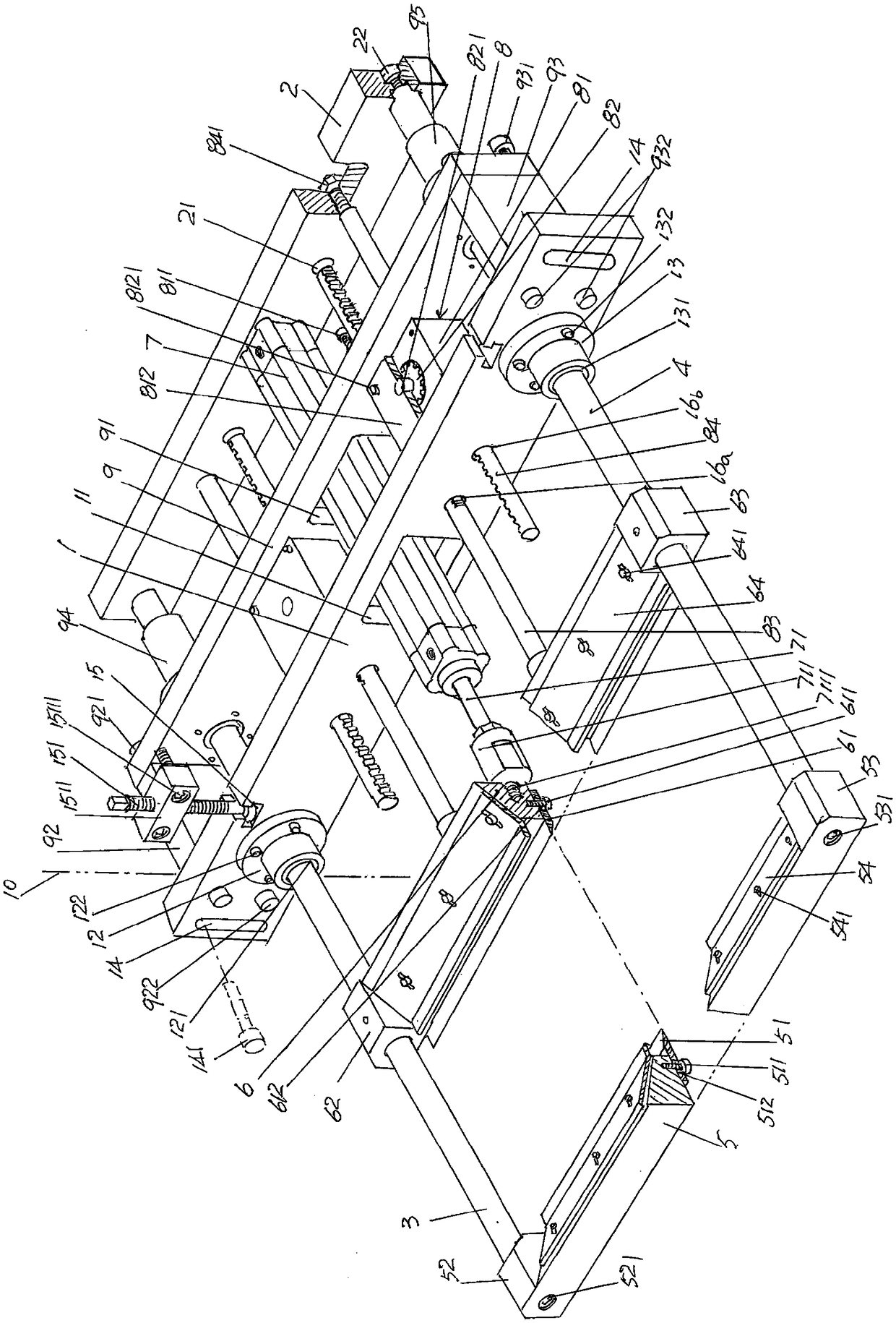
[0024] In the following descriptions, all concepts related to directionality or orientation of up, down, left, right, front and back are based on figure 1 The current position is a reference, so it cannot be understood as a special limitation on the technical solution provided by the present invention.

[0025] See figure 1 , shows a frame 10 of the structural system of the blow molding machine, and shows the following parts of the structural system of the parison cold-cutting encapsulation device: a fixed plate 1, which is in use with the aforementio...


PUM


Abstract

The invention provides a parison cold cutting and sealing device of a blow molding machine. The blow molding machine comprises a frame; the parison cold cutting and sealing device comprises a fixed plate which is fixed with the frame, a linkage plate corresponding to the rear side of the fixed plate, a left guide rod matched with a fixed plate left bearing seat, a right guide rod matched with a fixed plate right bearing seat, a front cutter frame, an acting cylinder and a pair of gear boxes; a front cutter is arranged at the bottom of the front cutter frame; a rear cutter is arranged at the bottom of the rear cutter frame; the linkage plate is fixed with the rear ends of the left guide rod and the right guide rod; the tail of the acting cylinder is fixed with the middle part of the front side of the linkage plate; each gear box comprises a box body, a gear, a rear cutter frame connection rack and a linkage plate connection rack; the parison cold cutting and sealing device also comprises a box body synchronous moving plate which is arranged between the left guide rod and the right guide rod and is connected or disconnected with the rear side of the fixed plate; a box body synchronous moving plate avoiding hole is formed in the middle part of the box body synchronous moving plate; the acting cylinder passes through the box body synchronous moving plate avoiding hole; the box bodies are fixed with one side of the box body synchronous moving plate. The parison cold cutting and sealing device of the blow molding machine is high in safety and is capable of improving the inspection and maintenance efficiency and the inspection and maintenance quality.

Description

technical field [0001] The invention belongs to the technical field of auxiliary facilities for blow molding machines of plastic hollow containers, and in particular relates to a parison cold cutting and encapsulating device of a blow molding machine. Background technique [0002] As known in the industry, in the process of forming a plastic hollow container by a plastic hollow container blow molding machine, the material in a molten state is blown out of the tubular blank by the primary inflation mechanism of the plastic hollow container molding machine, that is, the aforementioned The parison, the parison enters the mold set on the mold base of the mold opening and closing mechanism and is inflated by the needle blowing mechanism in the mold closing state (the industry calls it secondary inflation). Since the tubular blank is a continuous cylindrical body, it needs to be cut off once by the cold-cut encapsulation device arranged on the frame of the blow molding machine and...

Claims


Application Information

Patent Timeline
IPC IPC(8): B29C49/42
CPCB29C49/4252Y02P70/10
Inventor 贾辉李明黄裕王培安郭欢欢
Owner SUZHOU TONGDA MACHINERY
Why Eureka
Try Eureka