A high-voltage flip-chip LED chip structure and manufacturing method thereof

A technology of LED chips and manufacturing methods, which is applied in the direction of semiconductor devices, electrical components, circuits, etc., can solve the problems of leakage light emitting area between chip units, metal fracture at groove joints, metal migration, etc., to avoid metal migration and oxidation, Bridging Smooth, easy-to-bridge effects

Active Publication Date: 2019-11-22
盐城东紫光电科技有限公司
View PDF6 Cites 0 Cited by
  • Summary
  • Abstract
  • Description
  • Claims
  • Application Information

AI Technical Summary

Problems solved by technology

[0011] In view of the above-mentioned shortcomings of the prior art, the purpose of the present invention is to provide a new high-voltage flip-chip LED chip structure and its manufacturing method, which is used to solve the problem that trenches are used as isolation regions in the prior art, and trench connections are prone to occur. Problems such as metal breakage, leakage between chip units, and light-emitting area caused by too wide trench width. In addition, in this case, the DBR structure is used instead of the metal reflector structure, which solves the problem that the metal reflector in the prior art is affected by changes in the external environment. The resulting metal migration and oxidation problems greatly improve the reliability and reflection efficiency of the LED chip

Method used


Image

  • A high-voltage flip-chip LED chip structure and manufacturing method thereof
  • A high-voltage flip-chip LED chip structure and manufacturing method thereof
  • A high-voltage flip-chip LED chip structure and manufacturing method thereof

Examples


Embodiment Construction

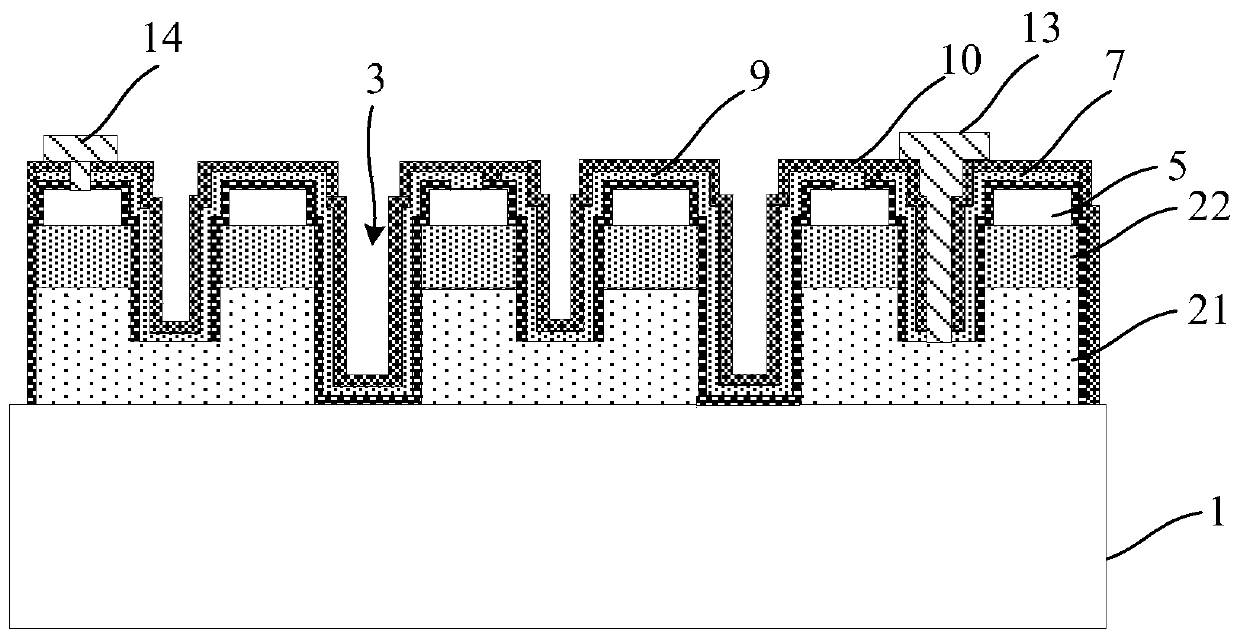
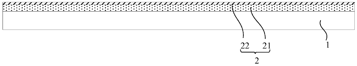
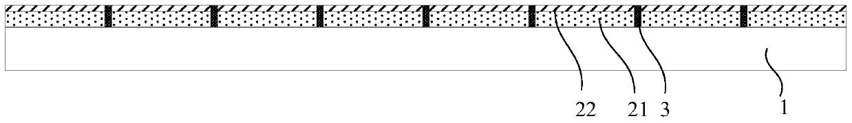
[0061] Embodiments of the present invention are described below through specific examples, and those skilled in the art can easily understand other advantages and effects of the present invention from the content disclosed in this specification. The present invention can also be implemented or applied through other different specific implementation modes, and various modifications or changes can be made to the details in this specification based on different viewpoints and applications without departing from the spirit of the present invention.

[0062] Please refer to attached picture. It should be noted that the diagrams provided in this embodiment are only schematically illustrating the basic idea of ​​the present invention, and only the components related to the present invention are shown in the diagrams rather than the number, shape and shape of the components in actual implementation. Dimensional drawing, the type, quantity and proportion of each component can be change...


PUM


Abstract

The invention provides a high-voltage flip LED (Light Emitting Diode) chip structure and a manufacturing method thereof. The manufacturing method comprises the steps of providing a growth substrate deposited with a GaN epitaxial layer; performing ion implantation to form a plurality of isolation areas, thus enabling the GaN epitaxial layer to form a plurality of mutually independent chip units, then performing mesa step etching, and forming a transparent electrode transmission layer; forming a DBR layer; forming an interconnection metal layer; forming insulating layer; and manufacturing N, P electrode bonding pads and the like. According to the high-voltage flip LED chip, the loss caused, which is caused by etching, in light emitting area of an light-emitting diode can be greatly reduced through performing ion implantation in the GaN epitaxial layer to form the plurality of isolation areas, bridge connection between chips can be enabled to be more gentle by using the isolation areas formed by ion implantation, and bridge connection between chips is performed more easily; In addition, the difference in height of a chip isolation area and other areas is small, the N, P electrode bonding pads are not easy to be conducted therebetween, the insulation effect is good, the yield in chip packaging is high, the difficulty of the packaging process is reduced, and the compatibility with a packaging frame is higher.

Description

technical field [0001] The invention belongs to the field of semiconductor lighting and relates to an LED chip structure and a manufacturing method thereof, in particular to a high-voltage flip-chip LED chip structure and a manufacturing method thereof. Background technique [0002] A light emitting diode (Light Emitting Diode, referred to as LED) is a semiconductor solid-state light-emitting device, which is made by using the principle of semiconductor P-N junction electroluminescence. LED devices have good photoelectric properties such as low turn-on voltage, small size, fast response, good stability, long life, and no pollution. Therefore, they are widely used in outdoor and indoor lighting, backlighting, display, traffic indication and other fields. [0003] There are three types of LED chip structures, namely horizontal structure (front mounted chip), vertical structure (vertical structure chip) and flip chip structure (flip chip); the flip chip structure means that the...

Claims


Application Information

Patent Timeline
Patent Type & Authority Patents(China)
IPC IPC(8): H01L33/10H01L33/32H01L33/04H01L33/42H01L33/20H01L33/00
CPCH01L33/0075H01L33/04H01L33/10H01L33/20H01L33/32H01L33/42
Inventor 齐胜利沈春生
Owner 盐城东紫光电科技有限公司
Why Eureka
Try Eureka