Power tool system

A power tool, voltage technology, applied in the field of power tool systems, can solve problems such as acceptance, power running time limit of cordless tools, etc.

Active Publication Date: 2017-08-18
BLACK & DECKER INC
View PDF20 Cites 10 Cited by
  • Summary
  • Abstract
  • Description
  • Claims
  • Application Information

AI Technical Summary

Problems solved by technology

Because cordless tools can be more limited in their power and/or run time, they are generally not accepted by the industry for many heavier duty applica

Method used


Image

  • Power tool system
  • Power tool system
  • Power tool system

Examples


Embodiment Construction

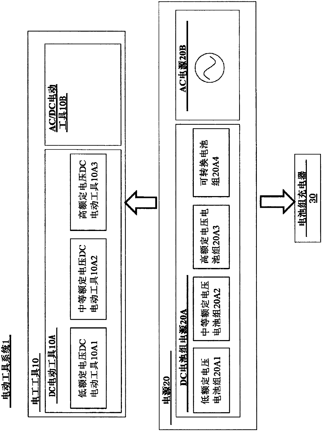
[0402] I. Power tool system

[0403] Such as Figure 1A As shown, in one embodiment, the power tool system 1 includes a set of power tools 10 (which includes a DC power tool 10A and an AC / DC power tool 10B), a set of power supplies 20 (which includes a DC battery pack power supply 20A and an AC power supply 20B) and a battery pack charger 30. Each of the power tools, power supplies, and battery pack chargers can be said to have a rated voltage. As used in this application, a rated voltage may refer to one or more of an advertised voltage, an operating voltage, a nominal voltage, or a maximum voltage, depending on the context. A rated voltage may also include a single voltage, several separate voltages, or one or more voltage ranges. As used in this application, a rated voltage may refer to any of these types of voltages or any type of range of these types of voltages.

[0404] Notified voltage. With respect to power tools, battery packs, and chargers, the advertised volta...


PUM


Abstract

A power tool system (1) includes a first power tool (10A1) having a first power tool rated voltage, a second power tool (10A2, 10A3, 10B) having a second power tool rated voltage that is different from the first power tool rated voltage, and a first battery pack (20A4) coupleable to the first power tool (10A1) and to the second power tool (10A2, 10A3, 10B). The first battery pack (20A4) is switchable between a first configuration having a first battery pack rated voltage that corresponds to the first power tool rated voltage such that the first battery pack enables operation of the first power tool (10A1), and a second configuration having a convertible battery pack rated voltage that corresponds to the second power tool rated voltage (10A2) such that the battery pack enables operation of the second power tool (10A2, 10A3, 10B).

Description

[0001] Cross References to Related Applications [0002] This application claims priority under 35 U.S.C. §119 to U.S. Provisional Application No. 61 / 994,953, filed May 18, 2014, entitled "Power Tool System," filed May 19, 2014 U.S. Provisional Application No. 62 / 000,112, entitled "Power Tool System," filed September 5, 2014 U.S. Provisional Application No. 62 / 046,546, entitled "Convertable Battery Pack," filed February 20, 2015 U.S. Provisional Application No. 62 / 118,917, entitled "Convertible battery pack," filed Dec. 12, 2014 U.S. Provisional Application No. 62 / 091,134, entitled "Convertible battery pack," filed Feb. 11, 2015 U.S. Provisional Application No. 62 / 114,645, entitled "Transport for System for Convertible battery pack," filed May 19, 2014, and entitled "Cycle-by-Cycle Current Limit for Power Tools Having a Brushless Motor." Provisional Application No. 62 / 000,307 and U.S. Provisional Application No. 62 / 093,513, filed December 18, 2014, entitled "Conduction Band Co...

Claims


Application Information

Patent Timeline
IPC IPC(8): H02J7/02
CPCH02J7/02H02J7/0024B25F5/02H02J7/36H01M10/441H01M10/46H02P29/0241H01M10/4207H01M2220/30H02P25/14H01M10/425H02J7/0045H02J7/00045Y02P70/50H01M50/588H01M50/597H01M50/213H01M50/247H01M50/296H01M50/244Y02E60/10H02J5/00H02P29/00H02J7/00714H02J7/0029H02J7/007H02P27/08H02P29/024H02P29/032H02J7/0013B25F5/00H01M10/0445
Inventor 丹尼尔·J·怀特马修·J·维尔德曼迈克尔·维里帕斯约翰·C·万科安德鲁·E·西曼迈克尔·罗伯茨内森·J·奥斯波恩赖安·克莱阿尔弗雷德·M·艾德古塔·戈特斯曼巴纳普拉萨德·戈蒂菲利普·吉尔德尼古拉斯·J·加里巴尔迪布赖恩·E·弗里德曼迈克尔·K·福斯特约翰·D·考克斯丹尼尔·P·菲茨杰拉德
Owner BLACK & DECKER INC
Why Eureka
Try Eureka