
Wall-mounted display screen device

A display screen and wall-mounted technology, applied in the field of display screen, can solve the problems of complicated installation and disassembly steps, affecting the aesthetics, etc., and achieve the effects of easy disassembly, replacement, maintenance, time-saving and labor-saving installation, and convenient use.

Active Publication Date: 2017-08-22
江西鑫彩晨光电科技有限公司
View PDF5 Cites 0 Cited by
  • Summary
  • Abstract
  • Description
  • Claims
  • Application Information

AI Technical Summary

Problems solved by technology

[0002] Nowadays, display screens are widely used and have a wide range of uses. Display screens are usually installed on the wall or placed directly on the table. When they need to be installed on the wall, in order to increase the aesthetics or save space, the display screen will be embedded. In the wall, the existing installation method is to install a bracket on the wall to fix the display screen. The bracket cooperates with the display screen by adjusting bolts and other items to prevent the display screen from falling. The installation and disassembly steps are cumbersome, and the existing Embedded installation needs to be larger than the range of the display screen, so that the display screen can be inserted into the back of the display screen to adjust the adjustment bolts and other items at the rear of the display screen, which affects the aesthetics. Can't meet people's needs

Method used


Image

  • Wall-mounted display screen device
  • Wall-mounted display screen device
  • Wall-mounted display screen device

Examples


Embodiment Construction

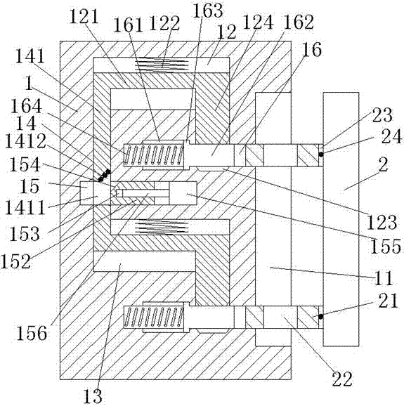
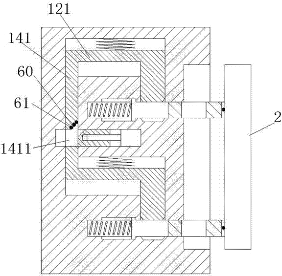
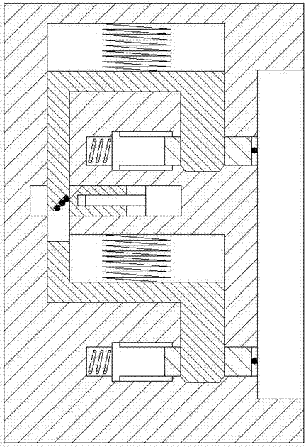
[0021] like Figure 1-Figure 5 As shown, a wall-mounted display device of the present invention includes a mounting frame 1 and a display screen 2, and the right side wall of the mounting frame 1 is provided with a sinking groove 11 for cooperating with the display screen 2, The installation frame 1 on the left side of the sinker 11 is provided with a first sliding cavity 12 and a second sliding cavity 13 which are symmetrical up and down, and the first sliding cavity 12 and the second sliding cavity 13 The installation frame 1 between them is provided with an open sliding cavity 15, and the opening sliding cavity 15 is provided between the left bottom of the first sliding cavity 12 and the left top of the second sliding cavity 13. The connecting groove 14 of the shifting chamber 15, the bottom of the right side of the first sliding chamber 12 and the second sliding chamber 13 are provided with a closing groove 123 elongated downwards, and the closing groove 123 is provided wi...


PUM


Abstract

The invention discloses a wall-mounted display screen device. The wall-mounted display screen device comprises a mounting rack and a display screen, wherein a sinking groove which is connected with the display screen in a matched manner is formed in the right side wall of the mounting rack; a first slipping cavity and a second slipping cavity are symmetrically formed in the mounting rack vertically and positioned on the left side of the sinking groove; an opening slipping cavity is formed in the mounting rack and positioned between the first slipping cavity and the second slipping cavity; a communication groove which communicates with the opening slipping cavity is formed between the bottom of the left side of the first slipping cavity and the top of the left side of the second slipping cavity; closing grooves which extend downwards are respectively formed in the bottom of the right side of the first slipping cavity and the bottom of the right side of the second slipping cavity; each closing groove is provided with an aligning groove which communicates with the closing groove; each aligning groove extends in the left-right direction; the inside of each aligning groove is slidably connected with a sliding block; guide grooves are symmetrically formed in a left extension section of each aligning groove vertically; projections which extend into the corresponding guide grooves are symmetrically arranged on the left side of each sliding block vertically; and a right extension section of each aligning groove communicates with the mounting rack and communicates with the sinking groove. The wall-mounted display screen device is simple in structure; time and labor are saved during mounting of the wall-mounted display screen device; and the wall-mounted display screen device is convenient to maintain.

Description

technical field [0001] The invention relates to the technical field of display screens, in particular to a wall-mounted display screen device. Background technique [0002] Nowadays, display screens are widely used and have a wide range of uses. Display screens are usually installed on the wall or placed directly on the table. When they need to be installed on the wall, in order to increase the aesthetics or save space, the display screen will be embedded. In the wall, the existing installation method is to install a bracket on the wall to fix the display screen. The bracket cooperates with the display screen by adjusting bolts and other items to prevent the display screen from falling. The installation and disassembly steps are cumbersome, and the existing Embedded installation needs to be larger than the range of the display screen, so that the display screen can be inserted into the back of the display screen to adjust the adjustment bolts and other items at the rear of t...

Claims


Application Information

Patent Timeline
IPC IPC(8): F16M13/02F16M11/04
CPCF16M11/04F16M13/02
Inventor 陈佳佳
Owner 江西鑫彩晨光电科技有限公司
Learn More