Fabricated prefabricated shear wall and laminated slab node

A prefabricated shear and laminated slab technology, applied to walls, protective buildings/shelters, building components, etc., can solve the problems of cumbersome reinforcement, poor installation accuracy, and low construction efficiency, and improve integrity and earthquake resistance , reduce the difficulty of construction, and facilitate the effect of standardized production and installation

Pending Publication Date: 2017-08-29
广东省建科建筑设计院有限公司 +1
View PDF10 Cites 14 Cited by
  • Summary
  • Abstract
  • Description
  • Claims
  • Application Information

AI Technical Summary

Problems solved by technology

[0006] The purpose of the present invention is to provide a prefabricated prefabricated shear wall and laminated slab joint with better overall performance and seismic performance and high construction efficiency, which can overcome the construction efficiency of the existing assembled reinforced concrete shear wall and laminated slab structure system The shortcomings of not high, poor installation accuracy, and too cumbersome on-site tying of steel bars can reduce the number of on-site supports, improve the integrity and seismic performance of prefabricated reinforced concrete shear walls and laminated slab joints, and are suitable for widespread application in building structures

Method used


Image

  • Fabricated prefabricated shear wall and laminated slab node
  • Fabricated prefabricated shear wall and laminated slab node
  • Fabricated prefabricated shear wall and laminated slab node

Examples


Embodiment Construction

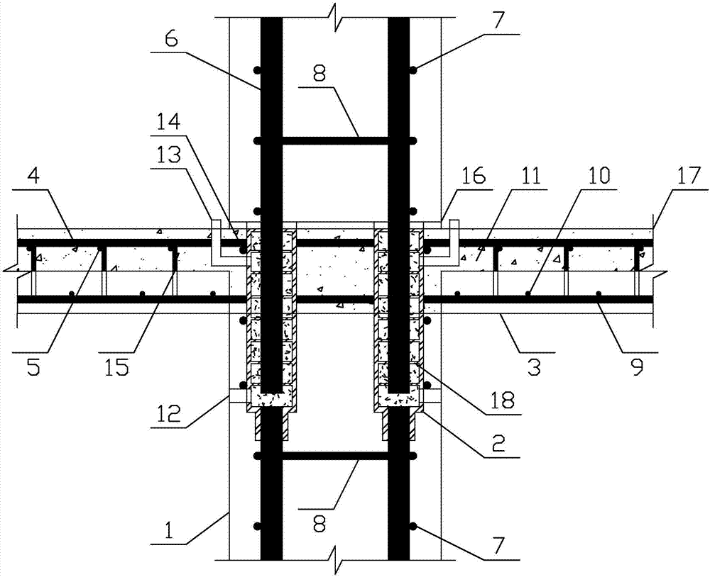
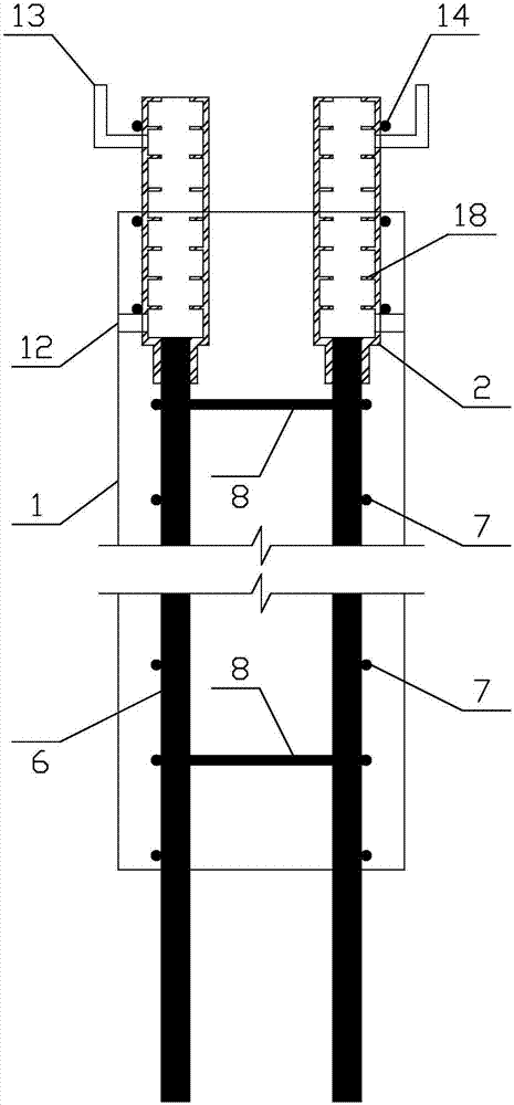
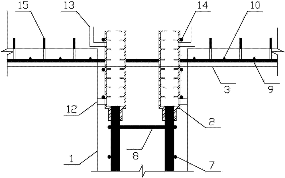
[0033] like Figure 1~4As shown, it is a prefabricated assembled shear wall and laminated slab joint of the present invention, including a prefabricated shear wall 1, a laminated slab 17 and a grouting sleeve 2, the prefabricated shear wall 1 is vertically arranged, and the prefabricated shear wall 1 is Reinforced concrete prefabricated wall, prefabricated shear wall 1 with grouting sleeve 2 extending from the upper end, and vertical steel bars 6 extending from the lower end; laminated slab 17 is mainly composed of prefabricated slab 3, steel mesh and post-cast concrete laminated layer 11, prefabricated slab 3 is set horizontally, the prefabricated slab 3 of the laminated slab is a reinforced concrete prefabricated slab, the steel bars are extended on both sides of the prefabricated slab 3, and the upper surface of the prefabricated slab 4 exposes the shear structural steel bars 15; the steel mesh is arranged horizontally above the prefabricated slab 3 And in the post-cast con...


PUM


Abstract

The invention discloses a fabricated prefabricated shear wall and laminated slab node. The fabricated prefabricated shear wall and laminated slab node comprises a prefabricated shear wall and a laminated slab; a grouting sleeve is arranged at a node body of the prefabricated shear wall and the laminated slab, the lower portion of the grouting sleeve is buried in the upper end of the prefabricated shear wall, and the rest part of the grouting sleeve is located in a post-poured concrete laminated layer of the laminated slab; the bottom end of the grouting sleeve is arranged at the top ends of vertical steel bars located in the prefabricated shear wall, the vertical steel bars downwards and outwards extend out of a prefabricated shear wall located on an upper floor, and the vertical steel bars are inserted into the grouting sleeve from the top end of the grouting sleeve; and a slurry discharging pipe and a grouting pipe are arranged on the upper portion and the lower portion of the grouting sleeve correspondingly, and a grouting material is poured into the grouting sleeve from the grouting pipe till the grouting material overflows from the slurry discharging pipe to enable the grouting sleeve to be completely filled with the grouting material. The grouting sleeve is a connecting piece of the upper-layer shear wall and the lower-layer shear wall, and a plastic hinge is formed at the bottom of the grouting sleeve. The prefabricated shear wall and a prefabricated plate form the wall plate node in an engaged mode through mutual connecting and binding among the grouting sleeve, a steel bar net piece and the post-poured concrete, and integrality and shock resistance of the node are improved.

Description

technical field [0001] The invention relates to an assembled prefabricated shear wall and laminated plate joint. Background technique [0002] Prefabricated reinforced concrete structures have already had many practical applications and relatively mature technical research in developed countries such as Europe, America and Japan. In recent years, the country has developed green buildings, vigorously developed prefabricated buildings, and promoted the transformation and upgrading of the construction industry. With the acceleration of the process of "building industrialization and housing industrialization" in my country, the application of prefabricated shear wall structures is becoming more and more extensive, and the practical application and theoretical research of prefabricated buildings in China is deepening. [0003] However, domestic research and application in this field is still in its infancy, and there is a lack of relevant norms and research guidance to support t...

Claims


Application Information

Patent Timeline
Patent Type & Authority Applications(China)
IPC IPC(8): E04B2/00E04B1/38E04H9/02E04B1/98
CPCE04B1/38E04B2/00E04H9/021
Inventor 徐其功徐天平刘亨杨国龙毛娜黄健耿凌鹏
Owner 广东省建科建筑设计院有限公司
Why Eureka
Try Eureka