Gas, dust explosion and explosion suppression experiment system applicable to various optical diagnosis methods

An optical diagnosis and dust explosion technology, which is applied in the field of explosion suppression experiment system, can solve the problems that the detection window or window is too small, cannot meet the application of laser-induced optical testing technology, and cannot be fully enclosed, and achieve high-precision timing control Effect

Active Publication Date: 2017-09-01
XIAN UNIV OF SCI & TECH
View PDF7 Cites 18 Cited by
  • Summary
  • Abstract
  • Description
  • Claims
  • Application Information

AI Technical Summary

Problems solved by technology

Optical combustion diagnosis technology has been widely used in combustion science experiments, but due to the special requirements of its test methods, the existing conventional explosion experimental equipment cannot meet its application conditions, so the application in the diagnosis of explosive transient combustion process is not mature enough
The existing devices still have deficiencies in the light transmission visibility and synchronous measurement and control of the reaction vessel, such as lack of detection window or too small window, low light transmittance, inappropriate installation location, or asynchronous ignition and optical signal measurement and control , a set of devices can only meet the problems of one optical testing technique, etc.
[0006] 1. It can only test the characteristics of combustible gas explosion/suppression propagation process from the macro level, such as the change of parameters such as temperature

Method used


Image

  • Gas, dust explosion and explosion suppression experiment system applicable to various optical diagnosis methods
  • Gas, dust explosion and explosion suppression experiment system applicable to various optical diagnosis methods
  • Gas, dust explosion and explosion suppression experiment system applicable to various optical diagnosis methods

Examples


Embodiment Construction

[0048] The technical solution of the present invention will be described in further detail below in conjunction with the accompanying drawings.

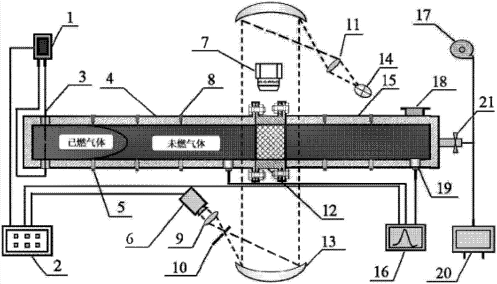
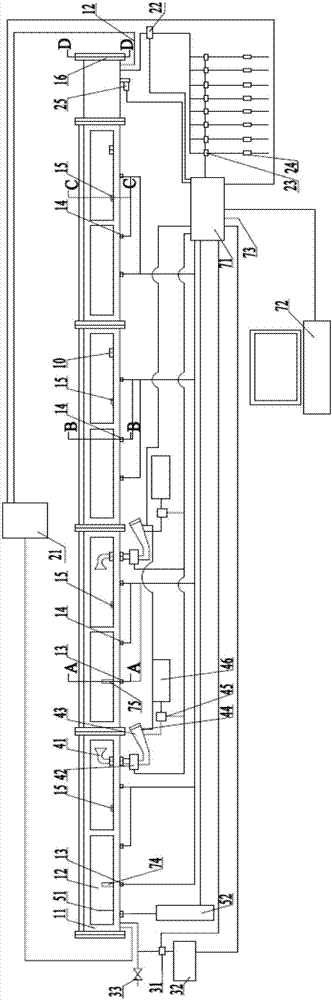
[0049] Such as Figure 2 to Figure 10 As shown, the gas and dust explosion and explosion suppression experimental system applicable to various optical diagnostic methods includes explosion pipes, vacuum system, gas distribution system, multiple powder spraying systems, ignition system, planar laser induced fluorescence system and main control system;

[0050] The explosion pipeline includes multiple pipeline units. The cross section of the pipeline unit is square. The bottom surface and skeleton of the pipeline unit are all made of steel to form a steel skeleton 11. Glass windows 12 are set on three sides. The transparent glass window 12 is made of high light transmittance. Imported fused silica, the length of each glass window 12 is not more than twice the width, so as to avoid deformation and shattering of the glass after being pre...


PUM


Abstract

The invention specifically relates to a gas, dust explosion and explosion suppression experiment system applicable to various optical diagnosis methods, solving the problems of an existing combustible gas, dust explosion and explosion suppression experiment system that the visibility is low, combustible gas explosion/explosion suppression propagation properties only can be tested from a macroscopic level, and application of an advanced optical measurement technology cannot be met. The experiment system comprises an explosion pipeline, a vacuum-pumping system, a gas distribution system, at least two powder spraying systems and an ignition system, and further comprises a planar laser-induced fluorescence system and a main control system. The invention provides the gas, dust explosion and explosion suppression experiment system applicable to the various optical diagnosis methods, which can be combined with a device for disclosing combustion explosion/explosion suppression propagation properties by microcosmic/macroscopic parameters and takes a steel framework and high-light-transmittance quartz glass as a main body structure.

Description

technical field [0001] The invention relates to an explosion suppression experiment system, in particular to a gas and dust explosion and explosion suppression experiment system applicable to multiple optical diagnosis methods. Background technique [0002] Combustion explosion is an important way for human beings to obtain energy. If it occurs in an uncontrolled time and space environment, it will bring huge loss of life and property to people. The explosion of combustible gas is mainly caused by the leakage of combustible gas, which is ignited by the fire source, and gradually forms turbulent combustion, deflagration or even detonation. Because of the huge destructiveness of combustible gas explosions, it is increasingly urgent to study the occurrence mechanism, damage mode and corresponding suppression methods of combustion explosions, and to propose disaster prevention and mitigation measures. Due to the destructiveness and danger of combustible gas explosions, conducti...

Claims


Application Information

Patent Timeline
IPC IPC(8): G01N25/54
CPCG01N25/54
Inventor 程方明罗振敏王涛王亚超苏彬邓军陈晓坤易欣王秋红李海涛
Owner XIAN UNIV OF SCI & TECH
Why Eureka
Try Eureka