
Temperature measurement method and system based on planar laser-induced fluorescence measurement device

A planar laser-induced, fluorescence measurement technology, applied in measurement devices, heat measurement, thermometers with physical/chemical changes, etc., can solve problems such as differences, and achieve comprehensive and accurate measurement results

Active Publication Date: 2022-03-01
SOUTHWEAT UNIV OF SCI & TECH +1
View PDF15 Cites 0 Cited by
  • Summary
  • Abstract
  • Description
  • Claims
  • Application Information

AI Technical Summary

Problems solved by technology

However, there are differences in the temperature of different flame positions during the combustion process of gunpowder. The existing temperature measuring device can only realize the measurement of certain positions, and cannot realize the comprehensive measurement of the entire combustion field of gunpowder combustion.

Method used


Image

  • Temperature measurement method and system based on planar laser-induced fluorescence measurement device
  • Temperature measurement method and system based on planar laser-induced fluorescence measurement device
  • Temperature measurement method and system based on planar laser-induced fluorescence measurement device

Examples


Embodiment 1

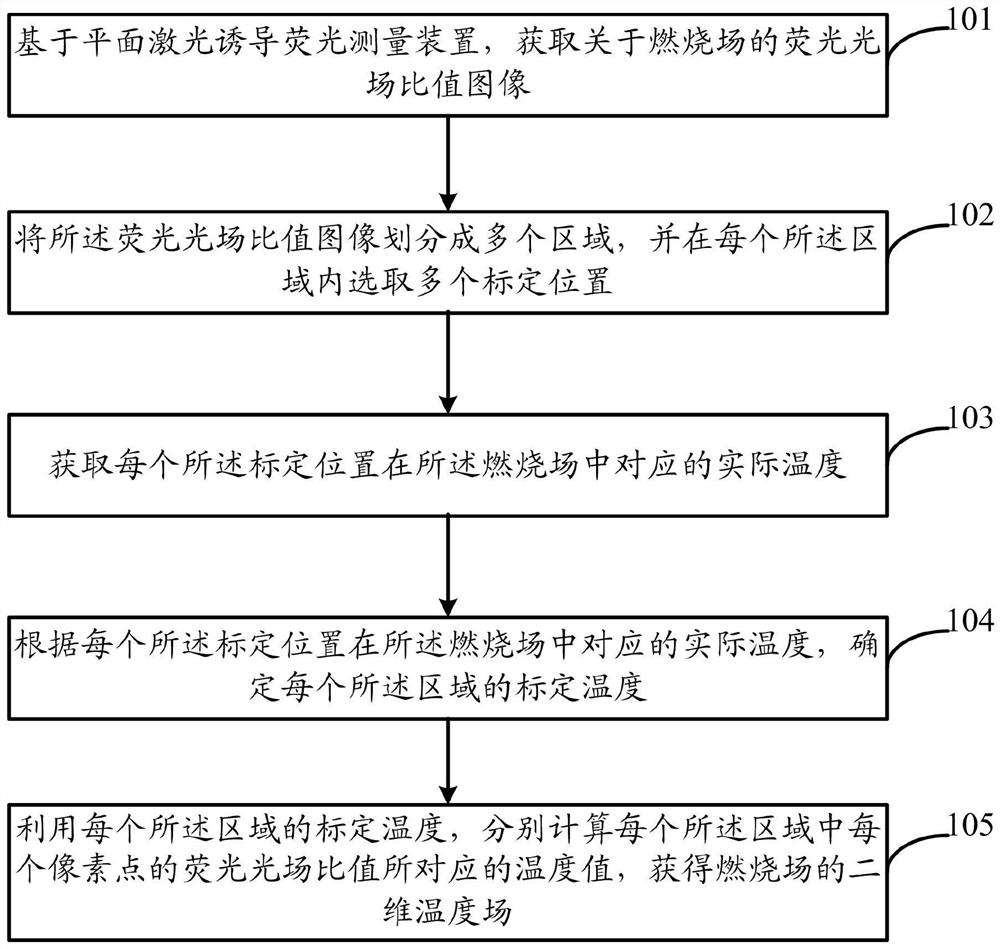
[0054] Such as figure 1 As shown, the present invention also provides a temperature measurement method based on a planar laser-induced fluorescence measuring device, and the temperature measurement method includes the following steps:

[0055] Step 101, based on the planar laser-induced fluorescence measurement device, obtain the fluorescence-light-field ratio image of the combustion field.

[0056] The fluorescence light field image F obtained by the image acquisition system using different wavelengths to excite the same combustion field 1 , F 2 , and use the formula (1) to get the fluorescence light field ratio image.

[0057]

[0058] In the formula, R is the fluorescence light field ratio image, F 1 , F 2 is the fluorescence light field image.

[0059] Step 102, dividing the fluorescent light field ratio image into multiple regions, and selecting multiple calibration positions in each of the regions.

[0060] Step 103, acquiring the actual temperature correspondin...

Embodiment 2

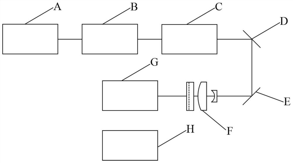
[0077] The present invention also provides a temperature measurement system based on a planar laser-induced fluorescence measurement device. The temperature measurement system includes: a planar laser-induced fluorescence measurement device, a combustion field temperature measurement device, and a temperature field acquisition device; the planar laser-induced fluorescence measurement The device is used to measure the fluorescence light field ratio image of the combustion field, and send the fluorescence light field ratio image of the combustion field to the fluorescence light field ratio image acquisition unit of the temperature field acquisition device; the temperature field acquisition device includes: the fluorescence light field ratio image The acquisition unit is used to acquire the fluorescence light field ratio image about the combustion field; the calibration position selection unit is used to divide the fluorescence light field ratio image into multiple areas, and selec...

Embodiment 3

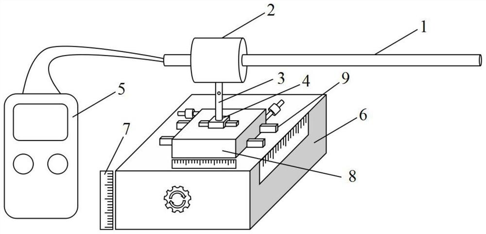
[0087] Such as figure 2 As shown, the combustion field temperature measuring device of the present invention includes a thermocouple temperature measuring device and a lifting translation platform device, wherein: the thermocouple temperature measuring device includes a thermocouple 1, a thermocouple fixing part 2, a support rod 3, and a fixed base connected in sequence 4 and a data thermometer 5; the thermocouple 1 is fixed on the thermocouple fixing part 2, the thermocouple fixing part 2 is fixed on the pole 3, the pole 3 is fixed on the fixed base 4, and the end of the thermocouple 1 is connected to the data thermometer 5.

[0088] The lifting and translation platform device includes a lifting platform 6, a standard ruler 7, a translation platform 8 and a pressing plate 9; the standard ruler 7 is vertically placed on one side of the lifting platform 6, and the translation platform 8 is fixed on the lifting platform 6 and fixed by the pressing plate 9. The two-dimensional t...


PUM


Abstract

The invention relates to a temperature measurement method and system based on a planar laser-induced fluorescence measurement device, and the method comprises the following steps: obtaining a fluorescence light field ratio image of a combustion field based on the planar laser-induced fluorescence measurement device; dividing the fluorescent light field ratio image into a plurality of areas, and selecting a plurality of calibration positions in each area; acquiring the actual temperature corresponding to each calibration position in the combustion field; according to the actual temperature corresponding to each calibration position in the combustion field, the calibration temperature of each area is determined; and respectively calculating a temperature value corresponding to the fluorescent light field ratio of each pixel point in each region by using the calibration temperature of each region. According to the invention, the fluorescence light field ratio image is divided into a plurality of areas, the calibration temperature of each area is determined in a multi-point measurement mode in the plurality of areas, and the temperature value corresponding to the fluorescence light field ratio of the pixel point is determined based on the calibration temperature, so that comprehensive and accurate measurement of the temperature of each position of the combustion field is realized.

Description

technical field [0001] The invention relates to the technical field of combustion field monitoring, in particular to a temperature measurement method and system based on a planar laser-induced fluorescence measurement device. Background technique [0002] In the field of aerospace, gunpowder is an important part of the aerospace field, and parameters such as temperature and combustion conditions during its combustion process are of great significance. However, there are differences in the temperature of different flame positions during the combustion of gunpowder. The existing temperature measuring device can only realize the measurement of some positions, and cannot realize the comprehensive measurement of the entire combustion field of gunpowder combustion. Contents of the invention [0003] The object of the present invention is to provide a temperature measurement method and system based on a planar laser-induced fluorescence measurement device, so as to realize compre...

Claims


Application Information

Patent Timeline
Patent Type & Authority Applications(China)
IPC IPC(8): G01K11/00
CPCG01K11/00
Inventor 邓琥逯勇旭徐司雨尚丽平赵凤起武志翔姚二岗刘泉澄熊亮屈薇薇李占锋
Owner SOUTHWEAT UNIV OF SCI & TECH
Learn More