
Planar Temperature Measurement Method Based on Planar Laser Induced Fluorescence Technology

A technology of plane laser induction and fluorescence technology, which is applied in the field of plane temperature measurement based on plane laser induction fluorescence technology, to achieve the effect of improving the compressive strength

Active Publication Date: 2020-10-09
AECC SHENYANG ENGINE RES INST
View PDF5 Cites 0 Cited by
  • Summary
  • Abstract
  • Description
  • Claims
  • Application Information

AI Technical Summary

Problems solved by technology

[0003] The purpose of this application is to provide a planar temperature measurement method based on planar laser-induced fluorescence technology to solve at least one of the above-mentioned problems

Method used


Image

  • Planar Temperature Measurement Method Based on Planar Laser Induced Fluorescence Technology
  • Planar Temperature Measurement Method Based on Planar Laser Induced Fluorescence Technology
  • Planar Temperature Measurement Method Based on Planar Laser Induced Fluorescence Technology

Examples


Embodiment Construction

[0024] In order to make the purpose, technical solution and advantages of the application more clear, the technical solution in the embodiment of the application will be described in more detail below in conjunction with the drawings in the embodiment of the application. In the drawings, the same or similar reference numerals denote the same or similar elements or elements having the same or similar functions throughout. The described embodiments are some, but not all, embodiments of the application. The embodiments described below by referring to the figures are exemplary, and are intended to explain the present application, and should not be construed as limiting the present application. Based on the embodiments in this application, all other embodiments obtained by persons of ordinary skill in the art without creative efforts fall within the protection scope of this application. Embodiments of the present application will be described in detail below in conjunction with th...


PUM


Abstract

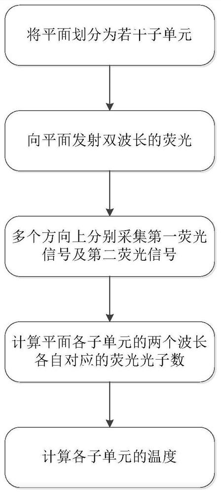
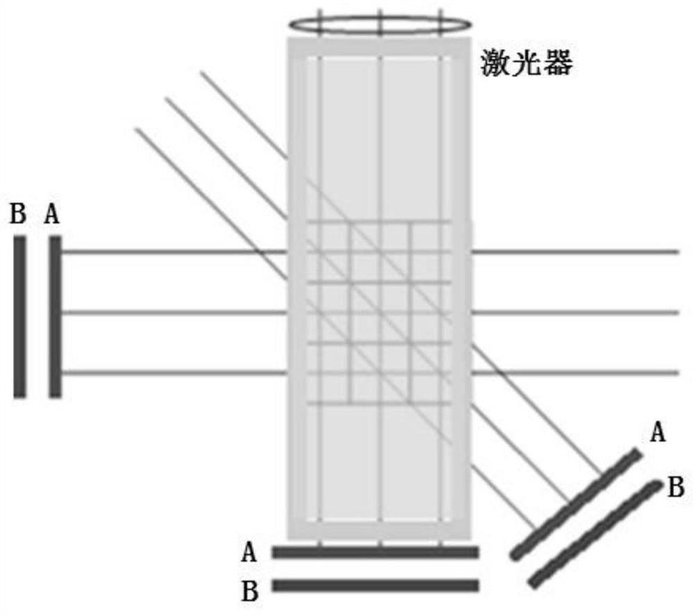
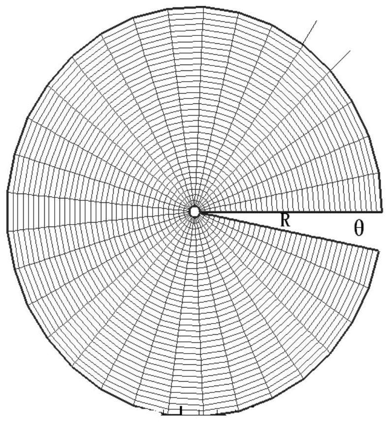
This application discloses a plane temperature measurement method based on plane laser-induced fluorescence technology, which belongs to the field of temperature measurement technology, including: step 1, dividing the plane into several subunits; step 2, emitting dual-wavelength fluorescence to the plane; step 3 1. Collecting the first fluorescence signal and the second fluorescence signal in multiple directions respectively; step 4, calculating the number of fluorescence photons corresponding to the two wavelengths of each subunit on the plane; and step 5, calculating the temperature of each subunit. Through this method, the measurement of the plane temperature field perpendicular to the airflow direction can be realized, the average temperature in a certain area of ​​the plane can be obtained, and the optical material with a smaller size can be used to improve the compressive strength.

Description

technical field [0001] The application belongs to the technical field of temperature measurement, and in particular relates to a plane temperature measurement method based on plane laser-induced fluorescence technology. Background technique [0002] Using the traditional planar laser-induced fluorescence temperature measurement technology, its CCD or CMOS camera can only be perpendicular to the measured section. The temperature field perpendicular to the axial direction cannot be measured by the existing technology, that is, the cross-sectional temperature field perpendicular to the airflow direction cannot be measured. At the same time, larger-sized pressure-resistant and temperature-resistant optical materials need to be used, and the cost is higher. Contents of the invention [0003] The purpose of the present application is to provide a planar temperature measurement method based on planar laser-induced fluorescence technology, so as to solve at least one of the above...

Claims


Application Information

Patent Timeline
Patent Type & Authority Patents(China)
IPC IPC(8): G01K11/32
CPCG01K11/32
Inventor 胡文成张宝华徐涛李学涛
Owner AECC SHENYANG ENGINE RES INST
Learn More