Eureka AIR delivers breakthrough ideas for toughest innovation challenges, trusted by R&D personnel around the world.

Multi-executing-mechanism compressor valve block punching machining device

A multi-actuating mechanism and processing device technology, applied in the field of mechanical processing, can solve problems such as troublesome operation, time-consuming and labor-intensive operations

Inactive Publication Date: 2017-09-08
WUHU XIAOSHENG ELECTROMECHANICAL TECH CO LTD
View PDF8 Cites 2 Cited by
  • Summary
  • Abstract
  • Description
  • Claims
  • Application Information

AI Technical Summary

Problems solved by technology

The shape and vent hole of the existing compressor valve plate are mostly punched and formed by punching dies, that is, the upper part of the die is a punch, and the lower part is a die with a punch. When stamping, the punch moves down to remove the raw material The piece is pressed into the die, and the punch is punched on the stamped piece at the same time. The punched waste falls from the punching groove of the punch and falls into the die. After the product is separated, the operation is troublesome, time-consuming and labor-intensive

Method used


Image

  • Multi-executing-mechanism compressor valve block punching machining device
  • Multi-executing-mechanism compressor valve block punching machining device
  • Multi-executing-mechanism compressor valve block punching machining device

Examples


Embodiment Construction

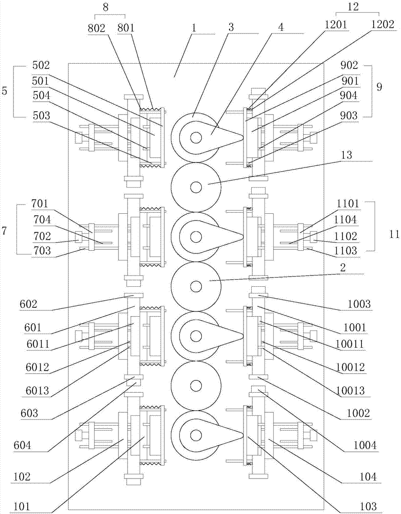
[0022] refer to Figure 1-Figure 3 , the present invention proposes a multi-executing mechanism compressor valve plate punching processing device, including a workbench 1, a power mechanism, a first punching actuator and a second punching actuator, wherein:

[0023]The power mechanism comprises a driving gear 2, a plurality of driven gears 3, a plurality of cams 4 and a first driving mechanism, the driving gear 2 and a plurality of driven gears 3 are all installed on the workbench 1, and the driving gear 2, a plurality of driven gears The gear 3 is linearly distributed along the length direction of the workbench 1 and a plurality of driven gears 3 are distributed on both sides of the driving gear 2. A transmission gear 13 is arranged between any adjacent two driven gears 3 and the two driven gears Driven gear 3 all meshes with this transmission gear 13, and two driven gears 3 closest to drive gear 2 all mesh with drive gear 2; The quantity of cam 4 is consistent with the quant...


PUM


Abstract

The invention provides a multi-executing-mechanism compressor valve block punching machining device. A first punching executing mechanism and a second punching executing mechanism are installed on a worktable and are arranged on the two sides of a power mechanism correspondingly. The first punching executing mechanism comprises first punching devices, wherein the number of the first punching devices is the same with that of cams. The second punching executing mechanism comprises second punching devices, wherein the number of the second punching devices is the same with that of the cams. Each first punching device and each second punching device correspond to one cam, wherein the direction of the connecting line of the first punching device and the second punching device is consistent with the width direction of the worktable. By means of the multi-executing-mechanism compressor valve block punching machining device, due to cooperation of the power mechanism, the first punching executing mechanism and the second punching executing mechanism, punching machining of multiple workpieces can be achieved at a time, one-time punching forming of products is achieved, automatic separation and discharging of punching waste and the products are achieved, a first discharging unit and a second discharging unit are used for disengaging the formed products from a first forming groove and a second forming groove, and the work efficiency is improved.

Description

technical field [0001] The invention relates to the technical field of mechanical processing, in particular to a multi-actuator compressor valve plate punching processing device. Background technique [0002] The valve plate of the compressor is placed at the exhaust port of the compressor. Its function is to close the refrigerant in the compressor, and the compressor compresses the refrigerant. When the compression pressure reaches a certain value, the valve plate is pushed open, and the compressed refrigerant flows from exhaust vent. The valve plate of the compressor is a plate structure, and many exhaust holes are arranged on it. The shape and vent hole of the existing compressor valve plate are mostly punched and formed by punching dies, that is, the upper part of the die is a punch, and the lower part is a die with a punch. When stamping, the punch moves down to remove the raw material The piece is pressed into the die, and the punch is punched on the stamped piece at...

Claims


Application Information

Patent Timeline
IPC IPC(8): B21D28/26B21D43/00B21D45/04
CPCB21D28/26B21D43/00B21D43/003B21D45/003
Inventor 汤长虎
Owner WUHU XIAOSHENG ELECTROMECHANICAL TECH CO LTD
Why Eureka
Eureka Blog
Learn More