Eureka AIR delivers breakthrough ideas for toughest innovation challenges, trusted by R&D personnel around the world.

Automatic blanking and punching forming machining device

A blanking punching and forming processing technology, applied in the field of mechanical processing, can solve the problems of time-consuming, laborious and troublesome operation, and achieve the effect of improving work efficiency and facilitating collection

Inactive Publication Date: 2017-07-07
WUHU XIAOSHENG ELECTROMECHANICAL TECH CO LTD
View PDF5 Cites 10 Cited by
  • Summary
  • Abstract
  • Description
  • Claims
  • Application Information

AI Technical Summary

Problems solved by technology

The shape and vent hole of the existing compressor valve plate are mostly punched and formed by punching dies, that is, the upper part of the die is a punch, and the lower part is a die with a punch. When stamping, the punch moves down to remove the raw material The piece is pressed into the die, and the punch is punched on the stamped piece at the same time. The punched waste falls from the punching groove of the punch and falls into the die. After the product is separated, the operation is troublesome, time-consuming and labor-intensive

Method used


Image

  • Automatic blanking and punching forming machining device
  • Automatic blanking and punching forming machining device
  • Automatic blanking and punching forming machining device

Examples


Embodiment Construction

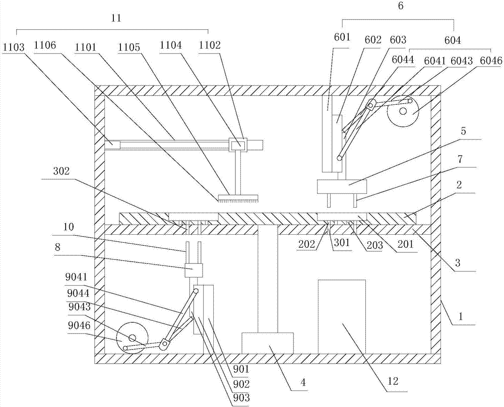
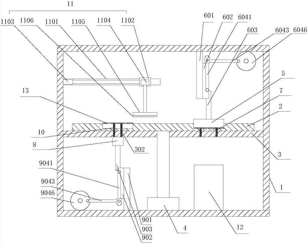
[0025] refer to figure 1 , figure 2 , the present invention proposes an automatic blanking punching forming processing equipment, comprising a frame 1, a workbench 2, a support platform 3, a driving mechanism 4, a punching mechanism, a material ejecting mechanism and a material sweeping mechanism 11, wherein:

[0026] The workbench 2 is arranged horizontally. The upper end of the workbench 2 is provided with N forming grooves 201, where N is a natural number and N≥1. The bottom of the forming groove 201 is provided with a plurality of first blanking holes 202 and A plurality of first ejector holes 203 run through its upper and lower surfaces.

[0027] The driving mechanism 4 is installed on the frame 1, and the driving mechanism 4 is connected with the workbench 2 so that the workbench 2 rotates.

[0028] The punching mechanism is located above the workbench 2 for punching the workpiece in the forming groove 201 , and the punching mechanism includes a punching die 5 and a f...


PUM


Abstract

The invention provides an automatic blanking and punching forming machining device. The device comprises a machine frame, a working table, a supporting table, a driving mechanism, a punching mechanism and an ejecting mechanism, wherein N forming grooves are formed in the upper end face of the working table, and the driving mechanism is connected with the working table and drives the working table to rotate; the punching mechanism is located above the working table and used for punching workpieces in the forming grooves; the ejecting mechanism is located below the working table and is used for ejecting the workpieces in the forming grooves; and the supporting table is located between the working table and the ejecting mechanism, the two ends of the supporting table are connected with the machine frame, and the upper end surface of the supporting table abuts against the lower end surface of the working table and is used for supporting the working table. According to the device, the punching mechanism, the working table and the supporting table are matched with one another, so that one-time punching forming of the product is realized, and the punching waste material is automatically separated from products; and the formed products are separated from the forming grooves by arranging the ejecting mechanism, so that the collecting is facilitated, and the working efficiency is improved.

Description

technical field [0001] The invention relates to the technical field of mechanical processing, in particular to an automatic blanking, punching and forming processing equipment. Background technique [0002] The valve plate of the compressor is placed at the exhaust port of the compressor. Its function is to close the refrigerant in the compressor, and the compressor compresses the refrigerant. When the compression pressure reaches a certain value, the valve plate is pushed open, and the compressed refrigerant flows from exhaust vent. The valve plate of the compressor is a plate structure, and many exhaust holes are arranged on it. The shape and vent hole of the existing compressor valve plate are mostly punched and formed by punching dies, that is, the upper part of the die is a punch, and the lower part is a die with a punch. When stamping, the punch moves down to remove the raw material The piece is pressed into the die, and the punch is punched on the stamped piece at t...

Claims


Application Information

Patent Timeline
Patent Type & Authority Applications(China)
IPC IPC(8): B21D28/34B21D28/36B21D45/04
CPCB21D28/34B21D28/36B21D45/006B21D45/04
Inventor 汤长虎
Owner WUHU XIAOSHENG ELECTROMECHANICAL TECH CO LTD
Why Eureka
Eureka Blog
Learn More