Eureka AIR delivers breakthrough ideas for toughest innovation challenges, trusted by R&D personnel around the world.

Continuous piercing equipment for valve block of compressor

A processing equipment and compressor technology, applied in the field of mechanical processing, can solve problems such as troublesome operation, time-consuming and labor-intensive problems

Inactive Publication Date: 2017-09-22
WUHU XIAOSHENG ELECTROMECHANICAL TECH CO LTD
View PDF6 Cites 2 Cited by
  • Summary
  • Abstract
  • Description
  • Claims
  • Application Information

AI Technical Summary

Problems solved by technology

The shape and vent hole of the existing compressor valve plate are mostly punched and formed by punching dies, that is, the upper part of the die is a punch, and the lower part is a die with a punch. When stamping, the punch moves down to remove the raw material The piece is pressed into the die, and the punch is punched on the stamped piece at the same time. The punched waste falls from the punching groove of the punch and falls into the die. After the product is separated, the operation is troublesome, time-consuming and labor-intensive

Method used


Image

  • Continuous piercing equipment for valve block of compressor
  • Continuous piercing equipment for valve block of compressor

Examples


Embodiment Construction

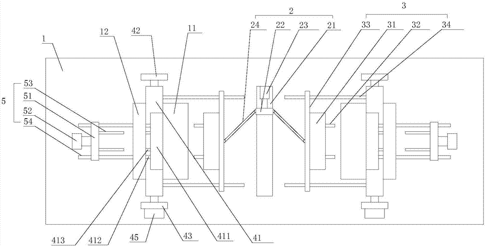
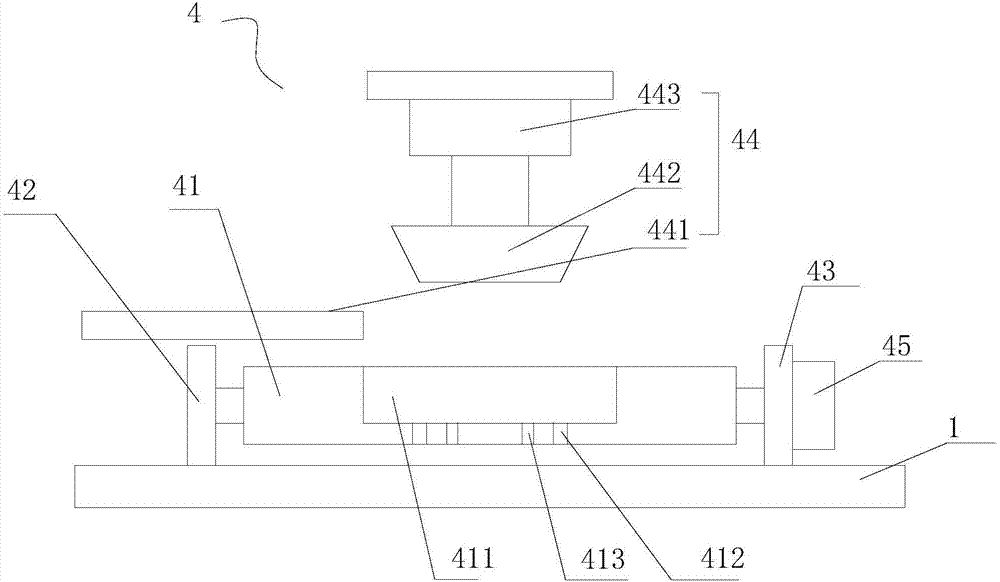
[0021] refer to figure 1 , figure 2 , the present invention proposes a continuous punching processing equipment for compressor valve plates, including a workbench 1, a first driving mechanism 2, two punching mechanisms 3, two fixing mechanisms 4 and two unloading mechanisms 5, wherein:

[0022] The first driving mechanism 2 is installed on the workbench 1 .

[0023] Two punching mechanisms 3 are respectively arranged on both sides of the first drive mechanism 2 and the connection direction of the two punching mechanisms 3 is consistent with the length direction of the workbench 1. The punching mechanism 3 includes a punching die 31 and a moving plate 33 And two first guide rails 34 installed on the workbench 1, the punching die 31 is provided with a punching head 32 away from the first driving mechanism 2 side, the extension direction of the first guide rail 34 is consistent with the length direction of the workbench 1, Both ends of the bottom of the moving plate 33 are con...


PUM


Abstract

The invention provides continuous piercing equipment for a valve block of a compressor. The continuous piercing equipment for the valve block of the compressor comprises a working table, a first driving mechanism, two piercing mechanisms, two fixing mechanisms and two unloading mechanisms, wherein the two piercing mechanisms are respectively arranged on two sides of the first driving mechanism; and the direction of a connecting line between the two piercing mechanisms is consistent to the length direction of the working table; each fixing mechanism is arranged on one side, which is away from the first driving mechanism, of the corresponding piercing mechanism; a forming groove is formed in a fixing plate of each fixing mechanism; a blanking hole matched with a corresponding piercing head and an unloading hole are formed in the bottom end of each forming groove; each fixing plate is connected with a second driving mechanism and is driven to rotate by the second driving mechanism; a feeding device is used for conveying to-be-processed workpieces to the forming groove of each fixing plate; and each unloading mechanism is arranged on one side, which is away from the corresponding piercing mechanism, of the corresponding fixing mechanism. By the first driving mechanism, the two piercing mechanisms, the two fixing mechanisms and the two unloading mechanisms, the workpieces are continuously pierced, and one-time piercing and forming of the product is realized.

Description

technical field [0001] The invention relates to the technical field of mechanical processing, in particular to continuous punching processing equipment for compressor valve plates. Background technique [0002] The valve plate of the compressor is placed at the exhaust port of the compressor. Its function is to close the refrigerant in the compressor, and the compressor compresses the refrigerant. When the compression pressure reaches a certain value, the valve plate is pushed open, and the compressed refrigerant flows from exhaust vent. The valve plate of the compressor is a plate structure, and many exhaust holes are arranged on it. The shape and vent hole of the existing compressor valve plate are mostly punched and formed by punching dies, that is, the upper part of the die is a punch, and the lower part is a die with a punch. When stamping, the punch moves down to remove the raw material The piece is pressed into the die, and the punch is punched on the stamped piece ...

Claims


Application Information

Patent Timeline
IPC IPC(8): B21D28/26B21D28/34B21D43/00B21D45/08
CPCB21D28/26B21D28/34B21D43/003B21D45/006B21D45/08
Inventor 汤长虎
Owner WUHU XIAOSHENG ELECTROMECHANICAL TECH CO LTD
Why Eureka
Eureka Blog
Learn More