AI technical title is built by PatSnap AI team. It summarizes the technical point description of the patent document.
A technology of intracavity devices and inner vertices, which is applied in the direction of surgical fixation nails, surgical forceps, prostheses, etc., and can solve the problems of increased time cost, risk, and high cost
Active Publication Date: 2017-09-15
INTACT VASCULAR
View PDF13 Cites 23 Cited by
Summary
Abstract
Description
Claims
Application Information
AI Technical Summary
This helps you quickly interpret patents by identifying the three key elements:
Problems solved by technology
Method used
Benefits of technology
Problems solved by technology
When one tries to place multiple stents and place multiple stents in the segment where implantation of the stent is most needed, the cost is very expensive because of the installation and material required for each stent
The time it takes to do so also adds cost and risk to the operation
Method used
Image
Click on the blue label to locate the original text in one second.
Reading with bidirectional positioning of images and text.
Examples
Embodiment approach
[0078] In these designs, for example in open and closed cell constructions, variations of plaque tacks 5 may have a mesh configuration and may be configured with one or more circumferential members formed from separate struts.
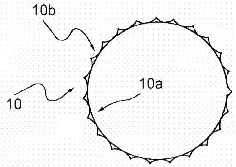
[0079] A. Plaque nails with metal mesh
[0080] An embodiment of a plaque tack 10 in the form of a metal mesh structure is as Figure 3A to Figure 3D shown. The plaque tack 10 is shown as having a closed cell structure with an annulus 10a formed of an interlaced mesh, and radially outwardly extending protrusions 10b. Plaque tacks 10 may be formed by laser cutting or etching a metal tube or made of thin metal wires looped and interlaced in a mesh, i.e. welded, brazed, looped and / or joined together to form as Figure 3C to Figure 3D The desired mesh shape is shown. The protrusion 10b may protrude from the endless belt 10a. The protrusion 10b may be on the outer surface of the staple and may be in contact with and / or embedded in the vessel wall.
...
PUM
Abstract
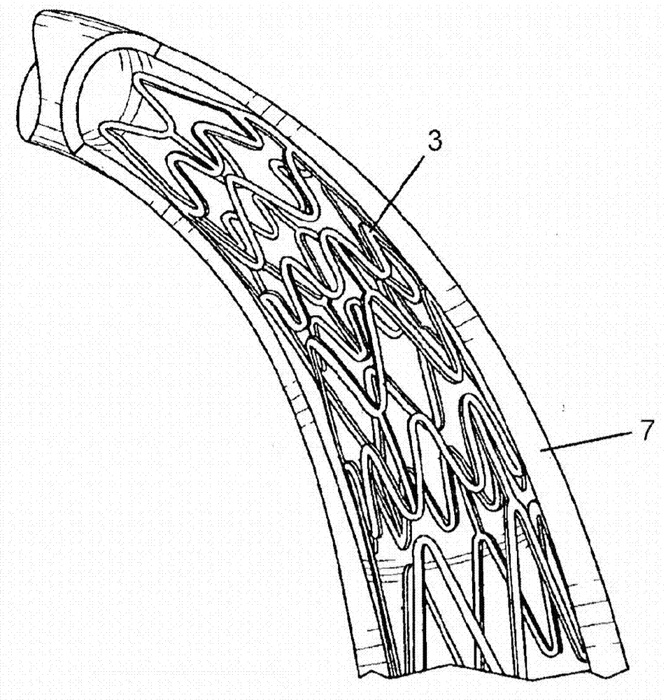
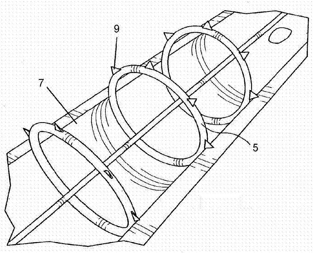
An endoluminal device can be configured for precise positioning during deployment within a vessel. The endoluminal device can be a tack, stent, vascular implant or other type of implant. The endoluminal device can have circumferential member with an undulating configuration having multiple inward and outward apexes and struts extending therebetween. Two of the struts can be used to establish a foot for the precise positioning of the device during deployment. A method of placing the endoluminal device can include withdrawing an outer sheath such that a portion of the endoluminal device is expanded prior to the rest of the endoluminal device.
Description
[0001] This application is a divisional application of a Chinese patent application with an application date of January 24, 2013, an application number of "201380014790.2", and an invention title of "Intracavitary Device and Method". The original application is the international application PCT / US2013 / 023030 Chinese national phase application. [0002] Cross References to Related Applications [0003] This application is a continuation-in-part of U.S. Application No. 13 / 179,458, filed July 8, 2011, which is a continuation-in-part of U.S. Application No. 13 / 153,257, filed June 3, 2011, which was filed on Continuation-in-Part of U.S. Application No. 13 / 118,388, filed May 28, 2011, which is a continuation-in-part of U.S. Application No. 12 / 790,819, filed May 29, 2010, which was filed June 2009 A continuation-in-part of US Application No. 12 / 483,193 filed on December 11, which is a continuation-in-part of US Application No. 11 / 955,331 filed December 12, 2007 (now US Patent No. 7,89...
Claims
Application Information
Patent Timeline
Application Date:The date an application was filed.
Publication Date:The date a patent or application was officially published.
First Publication Date:The earliest publication date of a patent with the same application number.
Issue Date:Publication date of the patent grant document.
PCT Entry Date:The Entry date of PCT National Phase.
Estimated Expiry Date:The statutory expiry date of a patent right according to the Patent Law, and it is the longest term of protection that the patent right can achieve without the termination of the patent right due to other reasons(Term extension factor has been taken into account ).
Invalid Date:Actual expiry date is based on effective date or publication date of legal transaction data of invalid patent.

