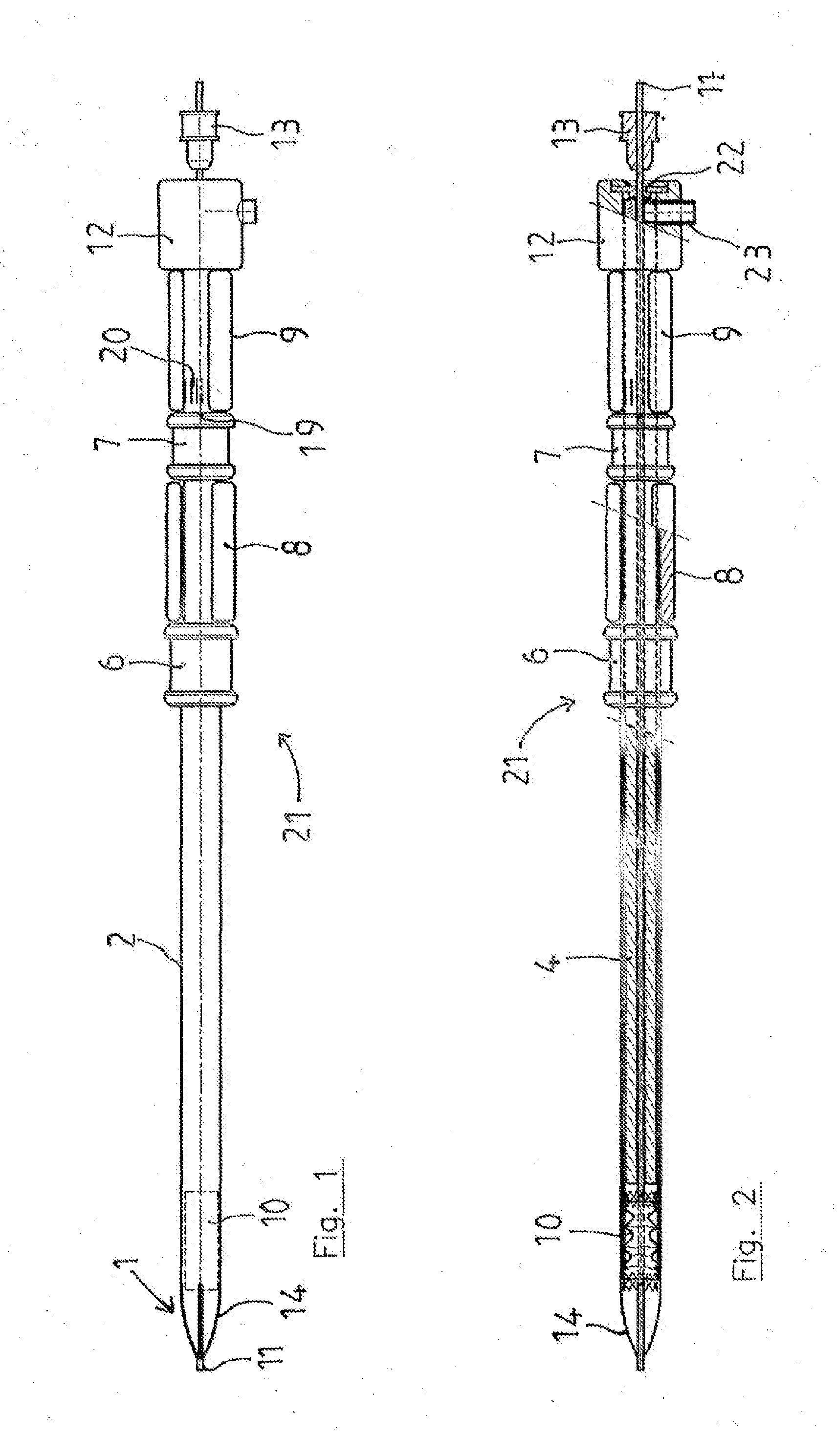
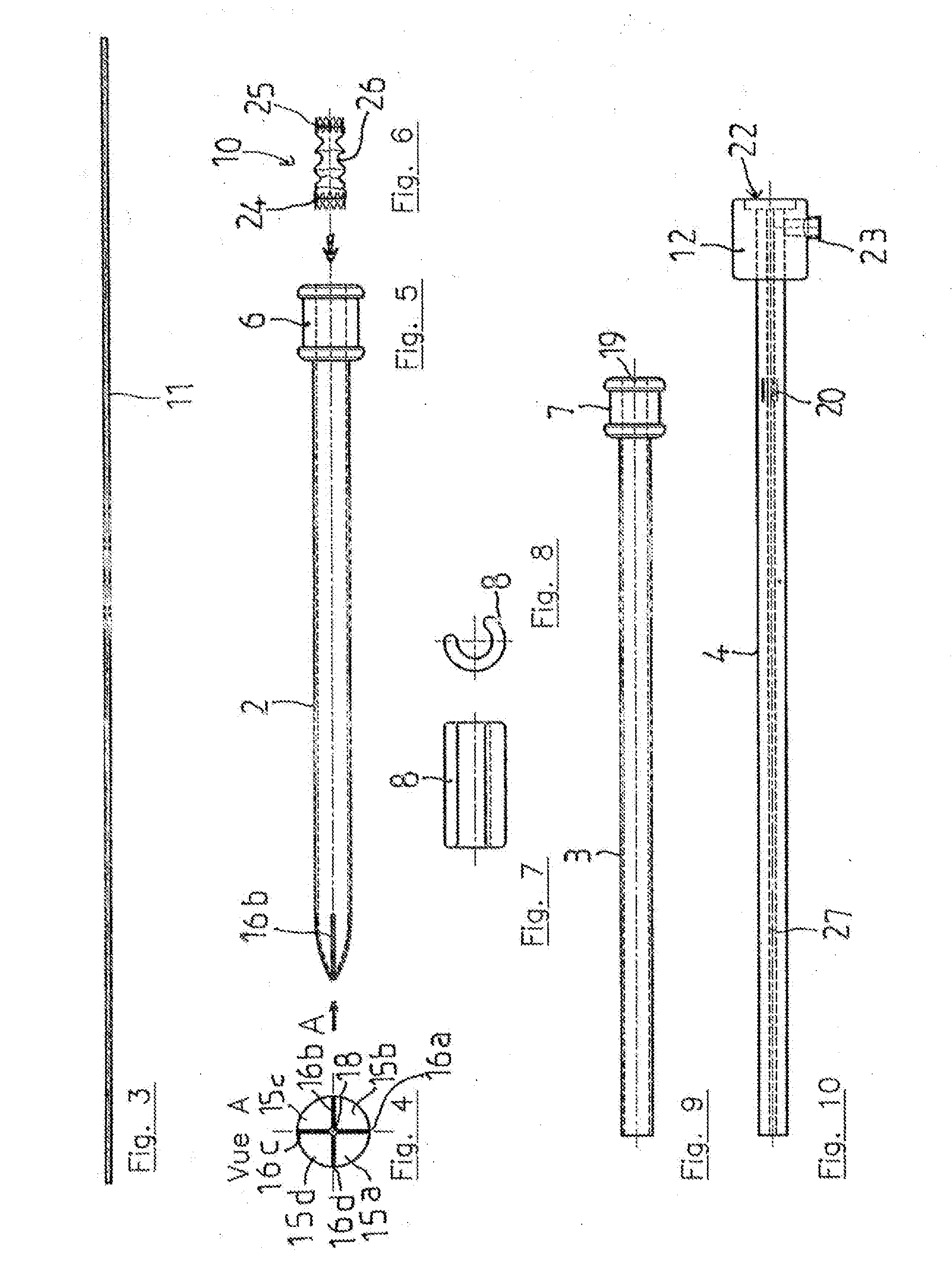
Device for placing a vascular implant

a technology for vascular implants and devices, applied in the field of devices for placing vascular implants, can solve the problems of unsuitable dilation instruments, damage to the internal wall of the vessels, and discontinuity in diameter, and achieve the effect of improving the safety and safety of patients

Inactive Publication Date: 2016-10-27
MIALHE CLAUDE
View PDF3 Cites 17 Cited by
  • Summary
  • Abstract
  • Description
  • Claims
  • Application Information

AI Technical Summary

Benefits of technology

[0023]It furthermore proves possible to perform several operations in the vessel during the same surgery: by forming a shape-memory system, the invention can provide a first insertion, and be closed again in order to reach another vascular section and to be re-employed therein.
[0024]The invention characteristically comprises a casin

Problems solved by technology

Another drawback of current inserters is that there remains a dimension transition zone between the internal tapered element and the external wall of the external sheath: this creates a discontinuity in diameter, which may be detrimental to the continuity of the insertion movement and damage the internal wall of the vessels.
The dilation instruments currently known prove

Method used


Image

  • Device for placing a vascular implant
  • Device for placing a vascular implant
  • Device for placing a vascular implant

Examples


Embodiment Construction

[0066]Various embodiments of the present invention are described in detail with reference to the accompanying drawings. The same or similar components may be designated by the same or similar reference numerals. Detailed descriptions of constructions or processes known in the art may be omitted to avoid obscuring the subject matter of the present invention.

[0067]The term dilation means, in the context of the invention, both:

[0068]the dilation of a narrowed area by a solid instrument of gradually increasing size. The tapered end makes it possible to effect a channel-type broadening by forcing the gradual separation of the walls or by extension of the separation of the tissues over the penetration area. The profile of the dilator also enables the instrument to be self-centered. This type of profile limits the risk of lesion of the internal wall of the vessels, often covered with calcified patches, use for “therapeutic” dilation as effected by the inflation of a balloon with endoprosth...


PUM


Abstract

Provided is an implant placement device that includes an envelope that contains an implant with a first auto-expandable element expandable in a radial direction, a nose at a distal end of the envelope, a sheath that confines a portion of the implant therein and restricts expansion of a second auto-expandable element of the implant, and a plunger. The sheath moves within the envelope in a longitudinal direction perpendicular to the radial direction and the plunger moves in the longitudinal direction within the sheath with the implant positioned between an end of the plunger and the nose, to discharge the implant from the device at a desired position. The sheath slides in the longitudinal direction towards the nose to bring the first auto-expandable element in contact with an interior of the plurality of slots, thereby opening the nose.

Description

PRIORITY[0001]This application is a Continuation Application of U.S. patent application Ser. No. 10 / 553,007, which was filed in the U.S. Patent and Trademark Office on Aug. 7, 2006, which is a National Phase Entry of International Application No. PCT / FRO4 / 50118, which was filed on Mar. 22, 2004, and claims priority to French Patent Application Serial No. 0350096, filed on Apr. 4, 2003, the entire disclosure of each of which is incorporated herein by reference.BACKGROUND OF THE INVENTION[0002]1. Field of the Invention[0003]The present invention relates to a device for placing an implant.[0004]2. Description of the Related Art[0005]In general, the related art includes the use of catheters or any other instrument for placing an implant in a vessel of the human or animal body.[0006]The invention may be used for placing objects in a vessel in the form of implants of the stent type or a vascular occlusion device as presented for example in the document WO-A-02 19 926, or implants of the c...

Claims


Application Information

Patent Timeline
IPC IPC(8): A61F2/966A61B17/12A61B17/00A61B17/34
CPCA61F2/966A61B17/12109A61B2017/1205A61F2002/9665A61B2017/00867A61B17/12172A61B17/0057A61B17/3415A61B17/3439A61B17/3468A61B2017/00575A61B2017/00592A61B2017/00606A61B2017/00623A61F2/95
Inventor MIALHE, CLAUDE
Owner MIALHE CLAUDE
Why Eureka
Try Eureka