Varying diameter vascular implant and balloon

a vascular implant and variable diameter technology, applied in the field of intravascular implants with variable diameter, can solve the problems of strain on the tissue, unsecure anchorage of the stent, etc., and achieve the effect of inhibiting the flow of blood

Inactive Publication Date: 2008-01-24
NEOVASC MEDICAL LTD
View PDF26 Cites 18 Cited by
  • Summary
  • Abstract
  • Description
  • Claims
  • Application Information

AI Technical Summary

Benefits of technology

[0009] In embodiments of the present invention, on the other hand, the balloon that is used to expand the implant has a diameter that varies over its length, in such a way as to roughly match the varying diameter of the body passage. When the implant is in place within the body passage, the balloon is inflated to plastically expand the implant, so that the expanded diameter of the implant roughly matches the full diameter of the body passage at two or more points, typically at both ends of the implant. (In the case of a constricting implant, as may be used in the cardiac sinus in order to partially constrict the flow of blood therethrough, a part of the implant, typically a central part, may remain unexpanded.) As a result, the implant is anchored securely in place, without undue strain on the walls of the body passage.
[0014] inflating the balloon so as to cause the implant to open, responsively to the varying radial dimension of the balloon, into an expanded shape that approximately matches the varying diameter of the body passage, thus anchoring the implant in the body passage.
[0023] In one embodiment, in which the body passage is a coronary sinus of a patient, choosing the balloon includes fitting the balloon to a widening region of the coronary sinus adjacent to a right atrium of the patient. Typically, the implant includes a constriction, and inflating the balloon includes expanding the implant to match the varying diameter of the coronary sinus except at the constriction, so as to inhibit a flow of blood through the coronary sinus.

Problems solved by technology

Therefore, if the diameter of the body passage varies over the length of the stent, the end of the stent in the wider area of the passage may be insufficiently expanded, so that the stent is not securely anchored.
Alternatively, the opposite end of the stent, in the narrower area of the body passage, may be expanded substantially beyond the natural diameter of the passage, causing strain on the tissue.

Method used


Image

  • Varying diameter vascular implant and balloon
  • Varying diameter vascular implant and balloon
  • Varying diameter vascular implant and balloon

Examples


Embodiment Construction

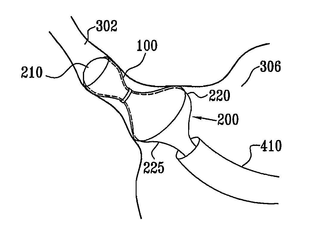
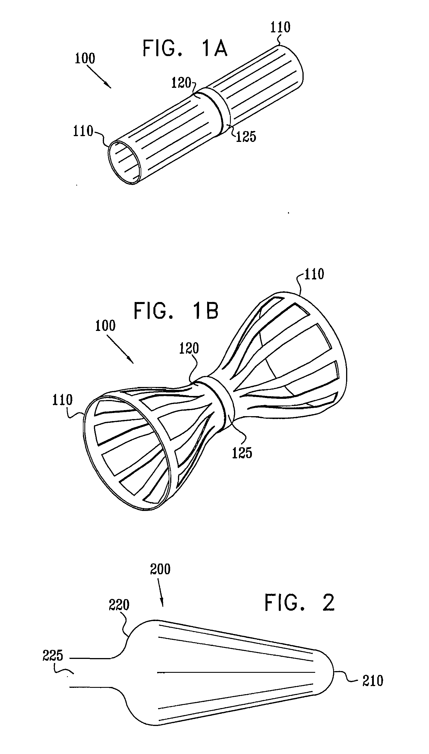
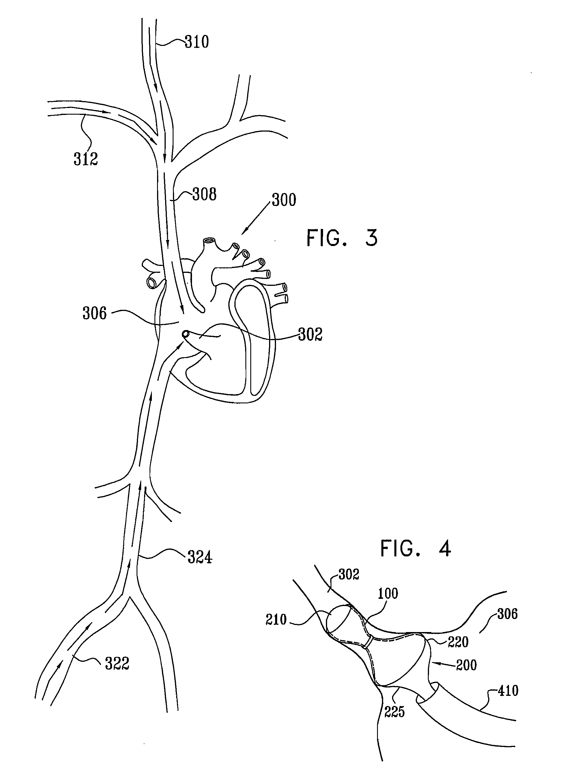
[0038] Reference is now made to FIGS. 1A and 1B, which are schematic, pictorial views of an exemplary implantable device 100, in a constricted state and an expanded state, respectively, in accordance with an embodiment of the present invention. Device 100 is adapted for use particularly in restricting blood flow through the coronary sinus, as described in the above-mentioned PCT Publication WO 01 / 72239 and U.S. patent application Ser. No. 09 / 534,968. Alternatively, devices in accordance with the principles of the present invention may be implanted elsewhere in the vascular system, as well as in other body passages. For the sake of simplicity and clarity, however, and not limitation, embodiments of the present invention are described hereinbelow with reference to implantation of flow-constricting devices in blood vessels of varying diameter, such as the coronary sinus.

[0039] Device 100 is of general tubular construction with two expandable ends 110 and a central section 120. Further...


PUM


Abstract

A method for deploying an expandable implant in a body passage of varying diameter includes selecting a balloon having a radial dimension that varies, when the balloon is inflated, in accordance with the varying diameter of the body passage. The balloon is inserted, in a deflated state, into the body passage, with the expandable implant fitted radially around the balloon. The balloon is inflated so as to cause the implant to open, responsively to the varying radial dimension of the balloon, into an expanded shape that approximately matches the varying diameter of the body passage, thus anchoring the implant in the body passage.

Description

CROSS-REFERENCE TO RELATED APPLICATIONS [0001] This application is a continuation-in-part of U.S. patent application Ser. No. 10 / 239,980, filed Sep. 26, 2002, in the national stage of PCT Patent Application PCT / IL01 / 00284, filed Mar. 27, 2001 (published as WO 01 / 72239). This application is also a continuation-in-part of U.S. patent application Ser. No. 11 / 170,748, filed Jun. 28, 2005, which is a continuation-in-part of PCT Patent Application PCT / IL03 / 00996, filed Nov. 25, 2003. The disclosures of all of these related applications are incorporated herein by reference.FIELD OF THE INVENTION [0002] The present invention relates generally to implantable therapeutic devices, and specifically to varying-diameter intravascular implants. BACKGROUND OF THE INVENTION [0003] Stent implants are commonly used in treating arterial stenoses and other unwanted constrictions of body passages. Stents typically comprise a metal coil or mesh. An arterial stent, for example, is threaded through the vasc...

Claims


Application Information

Patent Timeline
Patent Type & Authority Applications(United States)
IPC IPC(8): A61F2/06A61FA61F2/00A61F2/958
CPCA61F2/958A61M25/1002A61F2250/0039
Inventor BEN-MUVHAR, SHMUELSHALEV, ILANTSEHORI, JONATHANDARVISH, NISSIM
Owner NEOVASC MEDICAL LTD
Why Eureka
Try Eureka