a painting device

A technology for painting and equipment, applied in coatings, cleaning methods and utensils, chemical instruments and methods, etc., can solve the problems of high labor intensity for workers, poor accuracy of painting work, and volatilization of toxic gases, so as to improve the work of painting Precision, accurate painting work, high stability of the effect

Active Publication Date: 2019-06-18
浙江威荣精锻设备有限公司
View PDF6 Cites 0 Cited by
  • Summary
  • Abstract
  • Description
  • Claims
  • Application Information

AI Technical Summary

Problems solved by technology

[0002] In the production and processing of wood or ironware, the surface of the material is usually painted to make the material more corrosion-resistant and beautiful in appearance. Brushing refers to spraying the surface of the material evenly with a paint roller. Brushing is toxic. During the painting process, usually, the construction personnel carry out the painting work with a paint roller in hand. The labor intensity of the workers is high, time-consuming and laborious. After the painting work, the surface is uneven, the painting effect is poor, and the painting work is poor. During the process of material processing and painting, it is often impossible to effectively isolate the material automatically, which will cause the on-site toxic gas to volatilize, which not only pollutes the environment, but also causes great harm to the personal health of the operators.

Method used


Image

  • a painting device
  • a painting device
  • a painting device

Examples


Embodiment Construction

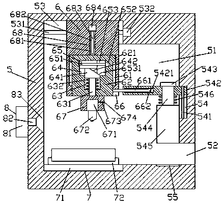
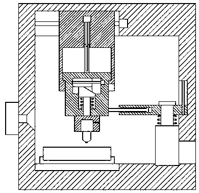
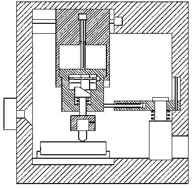
[0024] like Figure 1-Figure 5 As shown, a painting equipment of the present invention includes a frame 5, a painting cavity 51 is arranged in the frame 5, and a first movable groove 53 is arranged on the left side of the inner top of the painting cavity 51. The right side of the paint cavity 51 is provided with a second movable groove 54 , and the right side of the frame 5 under the second movable groove 54 is provided with an entrance 52 whose left end communicates with the paint brushing cavity 51 . The left and right sides of the inner bottom of the paint cavity 51 are respectively provided with a socket device 7 and a countersunk hole 55. The first movable groove 53 is provided with a first stud 531 extending left and right, and the first stud 531 is threaded. A movable block 6 whose bottom is pushed into the painting cavity 51 is matched and connected. The movable block 6 is provided with a first movable cavity 61, and the first movable cavity 61 is slidably connected wi...


PUM


Abstract

The invention discloses paint brushing equipment comprising a frame. A paint brushing cavity is formed in the frame. A first movable groove is formed in the left side of the top in the paint brushing cavity. A second movable groove is formed in the right side of the paint brushing cavity. An in-out opening with the left side end being connected with the paint brushing cavity in a communicating mode is formed in the right side, below the second movable groove, of the frame. The left and right sides of the bottom in the paint brushing cavity are provided with a sleeving device and a counterbored hole correspondingly. A first stud is arranged in the first movable groove in a horizontal extending mode. A movable block with the bottom being pushed in the paint brushing cavity is connected with the first stud in a thread fit mode. A first movable cavity is formed in the movable block. A fluctuation movable block is connected in the first movable cavity in a slide fit mode. Protruding heads connected with the interiors of the two sides of the first movable cavity in a slide fit mode are arranged on the tops of the two sides of the fluctuation movable block. The paint brushing equipment is simple in structure, convenient to operate, high in safety, capable of automatically controlling opening and closing of a partitioning plate, low in pollution, precise in paint brushing work and high in stability.

Description

technical field [0001] The invention relates to the field of painting, in particular to a painting device. Background technique [0002] In the production and processing of wood or iron, the surface of the material is usually painted to make the material more corrosion-resistant and beautiful in appearance. In the process of painting, usually, the construction personnel carry out the painting work with hand-held painting rollers. The workers are labor-intensive, time-consuming and labor-intensive. The surface after painting is uneven, the effect of painting is poor, and the accuracy of painting is poor. Traditional In the process of material processing and painting, it is often impossible to effectively isolate the material automatically, which will cause the volatilization of toxic gases on site, which not only pollutes the environment, but also causes great harm to the personal health of operators. SUMMARY OF THE INVENTION [0003] The technical problem to be solved by ...

Claims


Application Information

Patent Timeline
Patent Type & Authority Patents(China)
IPC IPC(8): B05C1/08B05C13/00B08B15/04
CPCB05C1/0821B05C13/00B08B15/04
Inventor 张雨晴
Owner 浙江威荣精锻设备有限公司
Why Eureka
Try Eureka