Automatic material receiving device

A material receiving device and automatic technology, applied in the field of automatic material receiving devices, can solve the problems of low production efficiency and high labor intensity of workers, and achieve the effects of improving the success rate, improving the material receiving efficiency, and preventing external leakage.

Inactive Publication Date: 2017-09-15
TIANJIN HONGXIANG PLASTIC PROD
1 Cites 0 Cited by

AI-Extracted Technical Summary

Problems solved by technology

[0003] At present, the work of arranging the disposable spoons 100 in the turnover box and moving them to the packaging ma...

Abstract

The invention provides an automatic material receiving device, the base is provided with a track, the material receiving mechanism is connected to the track, and the material receiving mechanism is respectively connected to the The controller is connected; the material receiving mechanism includes a slide seat, a rotating shaft, a material receiving sleeve, and several material receiving units. The slide seat is connected to the track, and one end of the rotating shaft is connected to the slide The seat is movably connected, and the other end is fixedly connected with the material receiving sleeve, and the material receiving unit is uniformly fixed on the material receiving sleeve. The material receiving frame of the invention is provided with a leak-proof extension, which prevents material leakage during material receiving, improves the success rate of material receiving, and reduces production loss.

Technology Topic

Image

  • Automatic material receiving device
  • Automatic material receiving device
  • Automatic material receiving device

Examples

  • Experimental program(1)

Example Embodiment

[0027] It should be noted that the embodiments of the present invention and the features of the embodiments may be combined with each other under the condition of no conflict.
[0028] In the description of the present invention, it should be understood that the terms "center", "longitudinal", "horizontal", "top", "bottom", "front", "rear", "left", "right", The orientation or positional relationship indicated by "vertical", "horizontal", "top", "bottom", "inside", "outside", etc. is based on the orientation or positional relationship shown in the drawings, and is only for the convenience of describing the present invention The description is created and simplified rather than indicating or implying that the device or element referred to must have a particular orientation, be constructed and operate in a particular orientation, and therefore should not be construed as limiting the invention. In addition, the terms "first", "second", etc. are used for descriptive purposes only, and should not be construed as indicating or implying relative importance or implying the number of indicated technical features. Thus, a feature defined as "first", "second", etc., may expressly or implicitly include one or more of that feature. In the description of the present invention, unless otherwise specified, "plurality" means two or more.
[0029] In the description of the present invention, it should be noted that, unless otherwise expressly specified and limited, the terms "installed", "connected" and "connected" should be understood in a broad sense, for example, it may be a fixed connection or a connectable connection. Detachable connection, or integral connection; may be mechanical connection or electrical connection; may be direct connection, or indirect connection through an intermediate medium, or internal communication between two components. For those of ordinary skill in the art, the specific meanings of the above terms in the present invention can be understood through specific situations.
[0030] The present invention will be described in detail below with reference to the accompanying drawings and in conjunction with the embodiments.
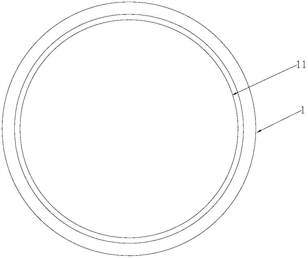
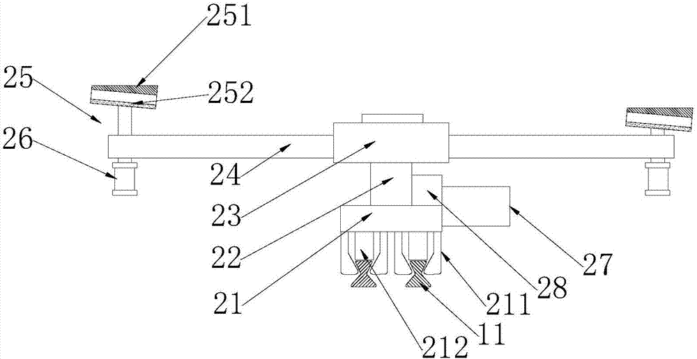
[0031] like Figure 1-4 As shown, an automatic feeding device includes a base 1, four feeding mechanisms 2, and a controller 5. The base 1 is provided with a track 11, and the feeding mechanism 2 is the same as the The rails 11 are connected, and the material receiving mechanism 2 is respectively connected with the controller 5 through lines;
[0032] The material receiving mechanism 2 includes a sliding seat 21, a rotating shaft 22, a material receiving sleeve 23, and eight material receiving units. The sliding seat 21 is connected to the track 11, and one end of the rotating shaft 22 is connected to the The sliding seat 21 is movably connected, and the other end is fixedly connected with the material receiving sleeve 23, and the material receiving unit is evenly fixed on the material receiving sleeve 23;
[0033] The feeding unit includes a feeding arm 24, a feeding frame 25, and a cylinder 26. One end of the feeding arm 24 is fixed on the feeding sleeve 23, and the other end is connected to the feeding frame 25. Connected, the cylinder 26 is connected with the material receiving frame 25 .
[0034] The feeding mechanism 2 is provided with a motor 27 and a reducer 28, the motor 27 is connected with the reducer 28 through a line, the reducer 28 is connected with the rotating shaft 22, and the The motor 27 is respectively connected with the sliding seat 21 , the cylinder 26 and the controller 5 through lines.
[0035] The material receiving frame 25 is inclined and provided with a leak-proof extension 251. The bottom of the leak-proof extension 251 is connected to the material receiving frame 25, and the top of the leak-proof extension 251 is connected to the material receiving frame 25. Horizontal planes are parallel.
[0036] The included angle between the material receiving frame 25 and the horizontal plane is 10°.
[0037] A buffer layer 252 is provided on the inner bottom of the material receiving frame 25 .
[0038] The base 1 is located on one side of the feeding mechanism 3, the distance between the base 1 and the feeding mechanism 3 is slightly larger than the length of the feeding arm 24, and the height of the top of the feeding mechanism 4 is slightly higher than The height of the feeding rack 25.
[0039] The bottom of the sliding seat 21 is provided with a reinforcing member 212 and two oppositely arranged connecting members 211 , and the reinforcing member 212 is located between the connecting members 211 .
[0040] The connecting piece 211 has an L-shaped structure, and the reinforcing piece 212 has a rectangular structure.
[0041] The cross section of the rail 11 is an hourglass-shaped structure, the connecting member 211 is fitted with the rail, and the reinforcing member 212 is located above the rail 11 .
[0042] The controller 5 controls the motor 27 to provide power for the material receiving mechanism 2, and the material receiving mechanism 2 slides on the track 11 cyclically. During the sliding process, the material receiving unit is driven by the rotating shaft 22 to rotate, and the material receiving frame 25 is in Driven by the air cylinder 26, it moves up and down; the material receiving rack 25 rotates to receive materials in turn. During material receiving, the material receiving rack 25 is located at the highest point, and the material receiving rack 25 starts to descend after receiving the material to transfer the material 4. To the packaging device; the number of feeding mechanisms 2 can be greater than or equal to the number of packaging devices, and the feeding mechanism 2 can correspond to one packaging device.
[0043] The above descriptions are only preferred embodiments of the present invention, and are not intended to limit the present invention. Any modification, equivalent replacement, improvement, etc. made within the spirit and principle of the present invention shall be included in the within the scope of protection of the present invention.

PUM

no PUM

Description & Claims & Application Information

We can also present the details of the Description, Claims and Application information to help users get a comprehensive understanding of the technical details of the patent, such as background art, summary of invention, brief description of drawings, description of embodiments, and other original content. On the other hand, users can also determine the specific scope of protection of the technology through the list of claims; as well as understand the changes in the life cycle of the technology with the presentation of the patent timeline. Login to view more.

Similar technology patents

Data receiving method and device

ActiveCN110278052AGuaranteed real-timeImprove receiving efficiencyNetwork traffic/resource managementReceiver specific arrangementsReal-time computing
Owner:DATANG MOBILE COMM EQUIP CO LTD

Apparatus for separating envelope and contents

InactiveCN105190713AImprove receiving efficiencyImprove reception processing efficiencyCoin/currency accepting devicesEnvelope openersEngineering
Owner:尹尚俊

Classification and recommendation of technical efficacy words

  • Improve receiving efficiency
  • Improve packaging efficiency

Scintillation crystal array detector and PET-MR system using the detector

ActiveCN103592671AReduce the number of reflectionsImprove receiving efficiencyX/gamma/cosmic radiation measurmentAcute angleScintillation crystals
Owner:SHANGHAI UNITED IMAGING HEALTHCARE

Raman spectroscopic detection apparatus

ActiveCN107014803AImprove receiving efficiencyHigh sensitivityRaman scatteringLaser lightRaman scattering
Owner:CHINA JILIANG UNIV

Double-layer grid mesh spherical secondary electronic collector

ActiveCN109100380AImprove receiving efficiencyShield interferenceMaterial analysis by measuring secondary emissionGrounding gridElectric field
Owner:INST OF FLUID PHYSICS CHINA ACAD OF ENG PHYSICS

Data receiving and sending method and terminal device

ActiveCN111756475AImprove receiving efficiencyReduce the number of blind detectionsParticular environment based servicesReceiver specific arrangementsEngineeringReal-time computing
Owner:HUAWEI TECH CO LTD

Full-automatic packing method

Owner:广东邦天智能制造有限公司
Why Eureka
Try Eureka