Matching circuit, matching circuit network and signal transmit-receive device

A matching circuit and network technology, applied in the direction of electrical components, transmission systems, etc., can solve the problem of high complexity of signal transceiver devices, achieve the effects of improving signal receiving efficiency, saving hardware resources, and reducing complexity

Active Publication Date: 2012-04-18
临沂经开财金投资发展有限公司
View PDF7 Cites 16 Cited by
  • Summary
  • Abstract
  • Description
  • Claims
  • Application Information

AI Technical Summary

Problems solved by technology

[0005] In view of this, the main purpose of the present invention is to provide a matching circuit, a matching circuit network and a signal transceiving device to solve the problem of high complexity of the existing signal transceiving device

Method used


Image

  • Matching circuit, matching circuit network and signal transmit-receive device
  • Matching circuit, matching circuit network and signal transmit-receive device
  • Matching circuit, matching circuit network and signal transmit-receive device

Examples


Embodiment 1

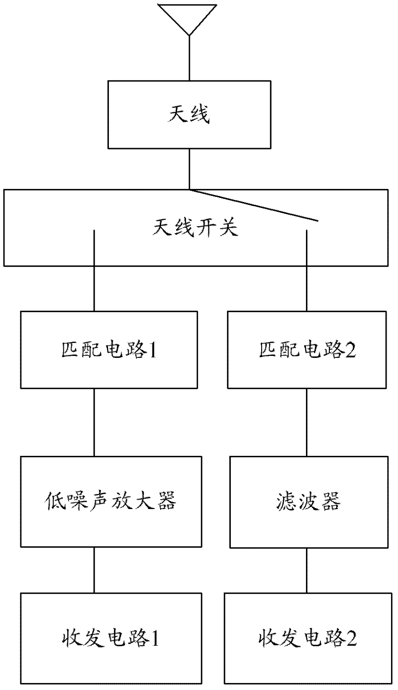
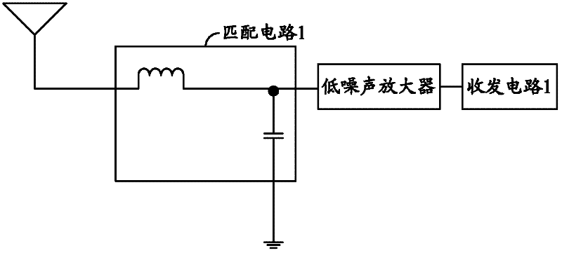
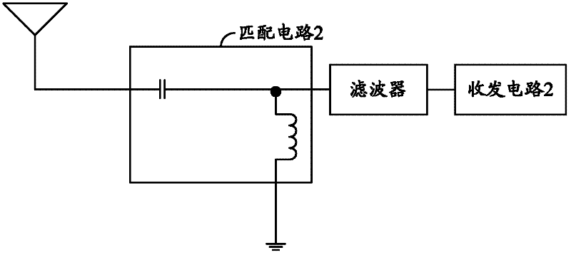
[0069] The signal transceiving device in this embodiment is as Figure 8 As shown, it mainly includes: an antenna, a high-frequency transmission branch, a low-frequency transmission branch, a first transceiver circuit and a second transceiver circuit, wherein the high-frequency transmission branch and the low-frequency transmission branch are connected in parallel between the antenna and the first transceiver circuit Between the circuit and the second transceiver circuit, the input end of the high frequency transmission branch and the input end of the low frequency transmission branch are connected to the antenna, and the output end of the high frequency transmission branch is connected to the second transceiver circuit , the output end of the low-frequency transmission branch is connected to the first transceiver circuit.

[0070] Wherein, the high-frequency transmission branch includes a first high-frequency matching circuit, and the low-frequency transmission branch include...

Embodiment 2

[0079] The signal transceiving device in this embodiment is as Figure 10 As shown, it mainly includes: an antenna, a high frequency transmission branch, a low frequency transmission branch and a transceiver circuit, wherein the high frequency transmission branch and the low frequency transmission branch are connected in parallel between the antenna and the transceiver circuit, and the high The input end of the high-frequency transmission branch and the input end of the low-frequency transmission branch are connected to the antenna, and the output end is connected to the transceiver circuit. The high-frequency transmission branch includes a first high-frequency matching circuit and a second high-frequency matching circuit, the low-frequency transmission branch includes a first low-frequency matching circuit and a second low-frequency matching circuit, and the transceiver circuit is used for receiving high-frequency signals and low-frequency signals.

[0080] Wherein, the first...

Embodiment 3

[0086] In practical applications, the high-frequency transmission branch and the low-frequency transmission branch of the signal transceiver device described in Embodiment 2 can be further subdivided, and the signal received by the antenna is matched and transmitted through four branches, so as to achieve The single-frequency antenna is respectively matched to the effect of four frequency bands, which improves the bandwidth of the antenna.

[0087] The signal transceiving device in this embodiment is as Figure 12 As shown, there are three matching circuit networks, one of which is a primary matching circuit network, and the other two are secondary matching circuit networks. The low-frequency transmission branch in the primary matching circuit network contains the first low-frequency matching circuit and the second The low-frequency matching circuit includes a first high-frequency matching circuit and a second high-frequency matching circuit on its high-frequency transmission ...


PUM


Abstract

The invention discloses a matching circuit, which comprises an isolating module, a filtering module and a matching module. The filtering module is connected between the isolating module and the matching module; the isolating module is used for isolating signals outside an assigned frequency and sending signals at the assigned frequency; the filtering module is used for filtering away the signals outside the assigned frequency; and the matching module is used for matching the signals at the assigned frequency. Correspondingly, the invention also discloses a matching circuit network and a signal transmit-receive device. The matching circuit, the matching circuit network and the signal transmit-receive device disclosed by the invention not only reduces complexity of the signal transmit-receive device, decreases cost and saves hardware resources, but also solves a problem that multiple paths of signals cannot be received at the same time in the case of using antenna switches and the like in the prior art and improves signal receiving efficiency.

Description

technical field [0001] The invention relates to signal receiving technology, in particular to a matching circuit, a matching circuit network and a signal transceiver. Background technique [0002] Multi-band antennas are very common in antenna design. Usually, one antenna is designed with different branches, so as to realize multi-band reception of a single antenna. However, with the increasing number of antennas on mobile phones, multi-antenna technology will consume a lot of area. In fact, with the development of antenna matching technology, the same antenna can meet the receiving requirements of different frequency bands when the matching parameters are different. Therefore, a single-frequency antenna cooperates with different antenna matching schemes to realize multi-band reception of the antenna. [0003] At present, the prior art realizes multi-band reception of a single antenna by using an antenna switch to switch to different matching circuits. figure 1 Shown is ...

Claims


Application Information

Patent Timeline
Patent Type & Authority Applications(China)
IPC IPC(8): H04B1/18H04B1/40
CPCH04B1/18H04B1/0458
Inventor 何文卿
Owner 临沂经开财金投资发展有限公司
Why Eureka
Try Eureka