Four-beam laser three-dimensional imaging optical system based on coaxial three-mirror-anastigmat afocal telescope

A technology of laser three-dimensional imaging and optical system, which is applied in the field of coaxial three-transverse afocal telescope, which can solve the difficulties of telescope selection and optical layout, the difficulty of achieving high-precision distance imaging, and the difficulty of obtaining large-scale lens materials, etc. problem, to achieve the effect of improving information acquisition efficiency, improving receiving efficiency, saving volume and weight

Inactive Publication Date: 2016-07-20
SHANGHAI INST OF TECHNICAL PHYSICS - CHINESE ACAD OF SCI
View PDF0 Cites 16 Cited by
  • Summary
  • Abstract
  • Description
  • Claims
  • Application Information

AI Technical Summary

Problems solved by technology

[0005] 1. The reflective receiving telescope has no chromatic aberration for the whole band, but the field of view of the two reflective systems is small, and it is difficult to form a detection channel with two beams or more than the field of view.
If the color separation film is used to split the same wavelength laser channel, the optical detection efficiency of each channel will be greatly weakened
[0006] 2 Due to the difficulty in obtaining large-scale lens materials, it is difficult to use transmission receiving telescopes in the field of spaceborne detection
[0007] 3 If an independent receiving telescope system is used, that is, one transmitting laser corresponds to one receiving system, the multi-beam receiving optics must correspond to more telescopes, which is a great pressure on spaceborne detectors limited by weight and volume
[0008] 4 It is difficult to have both high-resolution earth observation imaging and high-precision range imaging
If the detection of four laser channels is completed, the number of channels will reach 8, and the selection of telescopes and optical layout will be extremely difficult.

Method used


Image

  • Four-beam laser three-dimensional imaging optical system based on coaxial three-mirror-anastigmat afocal telescope
  • Four-beam laser three-dimensional imaging optical system based on coaxial three-mirror-anastigmat afocal telescope
  • Four-beam laser three-dimensional imaging optical system based on coaxial three-mirror-anastigmat afocal telescope

Examples


Embodiment Construction

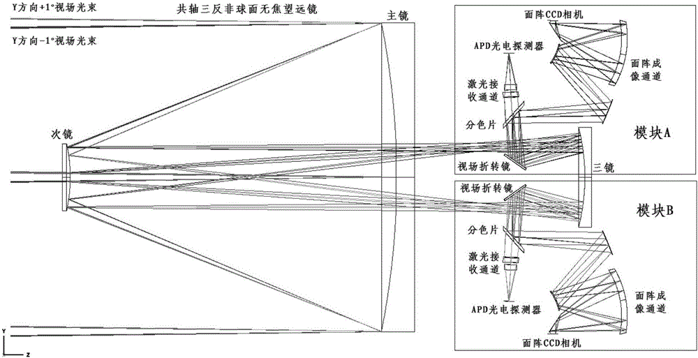
[0030] We have designed a laser four-beam three-dimensional imaging optical system based on a coaxial three-mirror afocal telescope. The image quality is close to the diffraction limit. The main technical indicators of the system are as follows:

[0031] 1 Visible light imaging and laser echo measurement can be performed on at least 4 laser beams;

[0032] 2 primary mirror diameter 500mm;

[0033] 3 spectral range: 400-900nm (visible light imaging) and 1064nm (laser imaging);

[0034]4 Spatial resolution: better than 5μrad, related to the detection distance, the focal length of the telescope system and the pixel size of the CCD camera. When the focal length of the telescope is 3.6m, the pixel size is 18 microns, and the detection distance is 700km, the spatial resolution can reach 3.5m;

[0035] 5 The F number of the optical system is 3.5;

[0036] 6 The field of view of two-dimensional surface object imaging reaches 0.5°×0.5°, the maximum field of view of absolute distorti...


PUM


Abstract

The invention discloses a four-beam laser three-dimensional imaging optical system based on a coaxial three-mirror-anastigmat afocal telescope. The four-beam laser three-dimensional imaging optical system is characterized in that: four paths of laser are scattered through a target surface, enter a novel coaxial three-mirror-anastigmat afocal telescope receiving system via four off-axis viewing fields respectively, are reflected through viewing field reflection mirrors, and adopt color separation filters for separating wave bands; and a laser receiving channel can achieve signal acquisition of laser echoes, and an area array imaging channel can achieve shooting of a laser footprint two-dimensional space target, thereby achieving multi-beam laser three-dimensional imaging. The four-beam laser three-dimensional imaging optical system solves the difficulty that multi-beam laser reflection loops share one receiving telescope in the existing laser active detection technology, the large viewing field coaxial three-mirror-anastigmat afocal telescope is adopted, the laser receiving channel and the area array imaging channel are combined by utilizing the off-axis viewing fields, and at least four beams of laser beam echoes can be measured on the layout.

Description

technical field [0001] The invention relates to a receiving optical system in the field of space-borne laser three-dimensional imaging, in particular to a coaxial triple-transverse afocal telescope form for receiving four-way laser echoes and high-resolution imaging of the earth. Background technique [0002] Laser three-dimensional imaging technology is a new active optical imaging technology, which refers to an imaging method that uses the two-dimensional distribution information of the target echo and the target distance information of the emitted laser signal to synthesize the target image. Since 3D images contain richer target information than 2D images, it is beneficial to identify target features with the help of target images, and even discover and identify camouflaged or hidden targets in the woods. Therefore, it is widely used in terrain surveying, urban construction, engineering construction, Environmental monitoring and other military and civilian fields have imp...

Claims


Application Information

Patent Timeline
Patent Type & Authority Applications(China)
IPC IPC(8): G01S17/89
CPCG01S7/4816G01S17/89Y02A90/10
Inventor 王欣姜守望万金龙黄庚华舒嵘何志平
Owner SHANGHAI INST OF TECHNICAL PHYSICS - CHINESE ACAD OF SCI
Why Eureka
Try Eureka