A Femtosecond Laser System Image Focusing Method

A technology of femtosecond laser and system image, which is applied in the field of femtosecond laser system image focusing, to achieve the effect of low requirements for experimental equipment and experimental environment, full field of view alignment, and easy realization

Active Publication Date: 2021-05-28
JILIN UNIV
View PDF0 Cites 0 Cited by
  • Summary
  • Abstract
  • Description
  • Claims
  • Application Information

AI Technical Summary

Problems solved by technology

However, after comprehensively considering factors such as the specific system layout and application requirements, each method has its own shortcomings.

Method used


Image

  • A Femtosecond Laser System Image Focusing Method
  • A Femtosecond Laser System Image Focusing Method
  • A Femtosecond Laser System Image Focusing Method

Examples


Embodiment 1

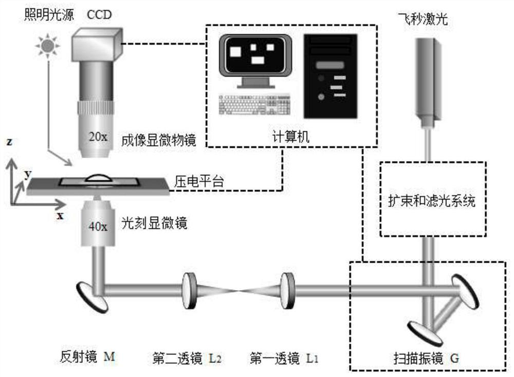
[0040] In the processing optical path of the femtosecond laser system, the laser focusing point on the substrate surface is found by the scratch method.

[0041] After the substrate is cleaned and glued, it is fixed on the processing platform, and ink marks are made on the non-glue area with a marker pen. Based on the femtosecond laser system to process the optical path, adjust the z-axis position of the microscope so that the laser can carve scratches on the ink marks. Repeat this operation until the light spot draws a uniform and uninterrupted continuous scratch on the ink mark, which indicates that the photolithography microscope focuses the laser spot on the upper surface of the substrate.

[0042] In the processing optical path of the femtosecond laser system, the laser focus point on the substrate surface is found by the scratch method. The specific steps are as follows:

[0043] (1), processing sample preparation:

[0044] The specific steps are as follows: wipe the m...

Embodiment 2

[0051] The cylindrical test structure is processed by the femtosecond laser system image focusing method.

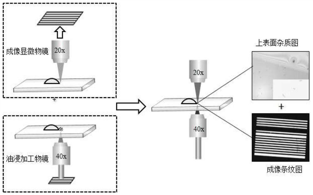
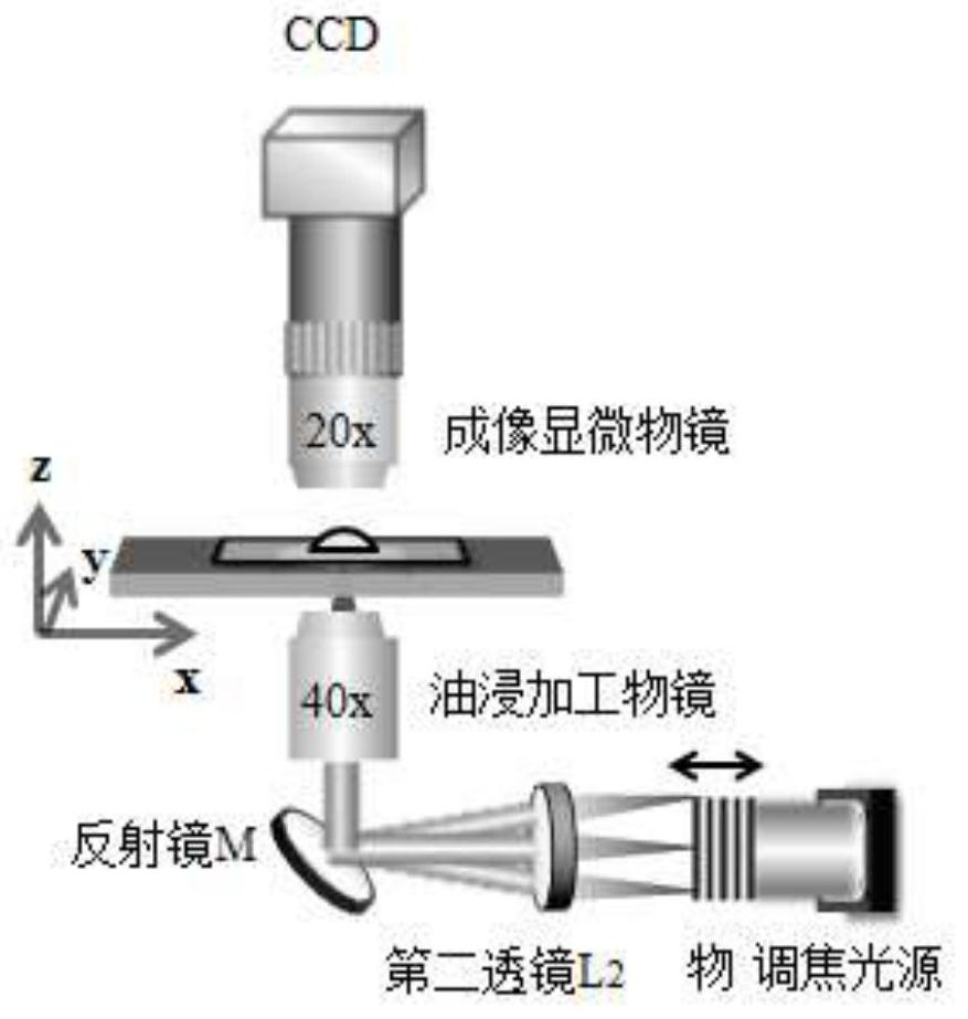
[0052] After finding the focus position of the laser spot by means of the laser across the ink marks on the surface of the substrate, and then based on this position, determine and fix the corresponding position of the object in the focusing optical path, and indirectly reflect the focus state of the laser with the clarity of the imaging state. If the CCD is at the same position, both a clear substrate surface and a clear fringe image can be observed, indicating that the focus is accurate. In subsequent processing, in order to make up for the height difference between different substrates, it is only necessary to fine-tune the z-direction position of the processing objective lens to make the fringes clear, then find the focal plane position and start processing. After the processing is completed, the substrate is processed and the processing results are analyzed.

[005...


PUM

PropertyMeasurementUnit
thicknessaaaaaaaaaa
lengthaaaaaaaaaa
widthaaaaaaaaaa

Abstract

The invention discloses a femtosecond laser system image focusing method, which belongs to the technical field of femtosecond laser system direct writing processing. The focus position of the laser spot is found by means of the laser across the ink marks on the surface of the substrate. Based on this, the CCD is fixed. , processing objective lens, piezoelectric platform three adjustment hardware, the position of the object as the only adjustment variable, determine and fix the corresponding position of the object in the focusing optical path, and indirectly reflect the laser focus state with the clarity of the imaging state. If the CCD is at the same position, both a clear substrate surface and a clear fringe image can be observed, indicating that the focus is accurate. In the subsequent processing, in order to compensate for the height difference between different substrates, it is only necessary to fine-tune the z-direction position of the processing objective lens to make the stripes clear. The focusing method of the present invention does not need to change the original optical path structure, and it is very easy to realize temporary construction and use. The operation steps are relatively simple, and the requirements for experimental instruments and experimental environment are not high, so it is easy to implement.

Description

technical field [0001] The invention belongs to the technical field of direct writing processing of a femtosecond laser system, and in particular relates to an image focusing method of a femtosecond laser system. Background technique [0002] Modern social science and technology are developing in the direction of "micro". Micro devices are widely used in various fields such as electronics, optics, machinery, biology, bionics, etc., and high-precision components are bound to put forward higher requirements for processing methods. Femtosecond laser processing technology stands out from other three-dimensional processing methods due to its wide range of processable materials and high processing accuracy, but it also has the problem of low processing efficiency. Therefore, whether the focusing operation before processing is simple and accurate is crucial to the entire processing process. [0003] Aiming at the focusing problem of the optical processing system, there are three k...

Claims


Application Information

Patent Timeline
Patent Type & Authority Patents(China)
IPC IPC(8): G02B21/24G02B21/33G02B21/36G02B21/00B23K26/046B23K26/064
CPCB23K26/046B23K26/0643B23K26/0648G02B21/0016G02B21/244G02B21/245G02B21/33G02B21/365
Inventor 陈岐岱刘华孙洪波
Owner JILIN UNIV
Why Eureka
Try Eureka