
Photoacoustic microscopy imaging system and method

A photoacoustic microscopy and imaging system technology, which is applied to material analysis, instruments, and measuring devices through optical means, can solve the problem of the huge difference between the longitudinal resolution and lateral resolution of photoacoustic imaging, which affects the sensitivity of photoacoustic wave detection and imaging. Depth, narrow detection bandwidth and other issues, to achieve the effect of improving vertical resolution, high bandwidth, and improving sensitivity

Active Publication Date: 2021-03-02
SHEN ZHEN SHEN GUANG SU TECH CO LTD
View PDF7 Cites 0 Cited by
  • Summary
  • Abstract
  • Description
  • Claims
  • Application Information

AI Technical Summary

Problems solved by technology

[0005] Among them, high resolution, high sensitivity and deeper imaging depth have always been the ultimate goal of developing imaging methods, but at present, photoacoustic waves excited by excitation light in photoacoustic imaging are generally received directly by ultrasonic transducers, and such detectors generally Made of piezoelectric ceramics, due to some properties of the material itself, its detection bandwidth is very narrow, so that the longitudinal resolution and lateral resolution of photoacoustic imaging are very different, and the resulting image is seriously distorted
Moreover, sound waves propagate in the form of spherical waves. When photoacoustic waves reach the ultrasonic transducer, most of the energy will diffuse into the medium, and only a small part can be received by the detector, which seriously affects the sensitivity and accuracy of photoacoustic wave detection. imaging depth

Method used


Image

  • Photoacoustic microscopy imaging system and method
  • Photoacoustic microscopy imaging system and method
  • Photoacoustic microscopy imaging system and method

Examples


Embodiment Construction

[0039] The following will clearly and completely describe the technical solutions in the embodiments of the present invention with reference to the accompanying drawings in the embodiments of the present invention. Obviously, the described embodiments are only part of the embodiments of the present invention, not all of them. The components of the embodiments of the invention generally described and illustrated in the figures herein may be arranged and designed in a variety of different configurations. Accordingly, the following detailed description of the embodiments of the invention provided in the accompanying drawings is not intended to limit the scope of the claimed invention, but merely represents selected embodiments of the invention. Based on the embodiments of the present invention, all other embodiments obtained by those skilled in the art without creative efforts shall fall within the protection scope of the present invention.

[0040] In the description of the pres...


PUM

PropertyMeasurementUnit
wavelengthaaaaaaaaaa

Abstract

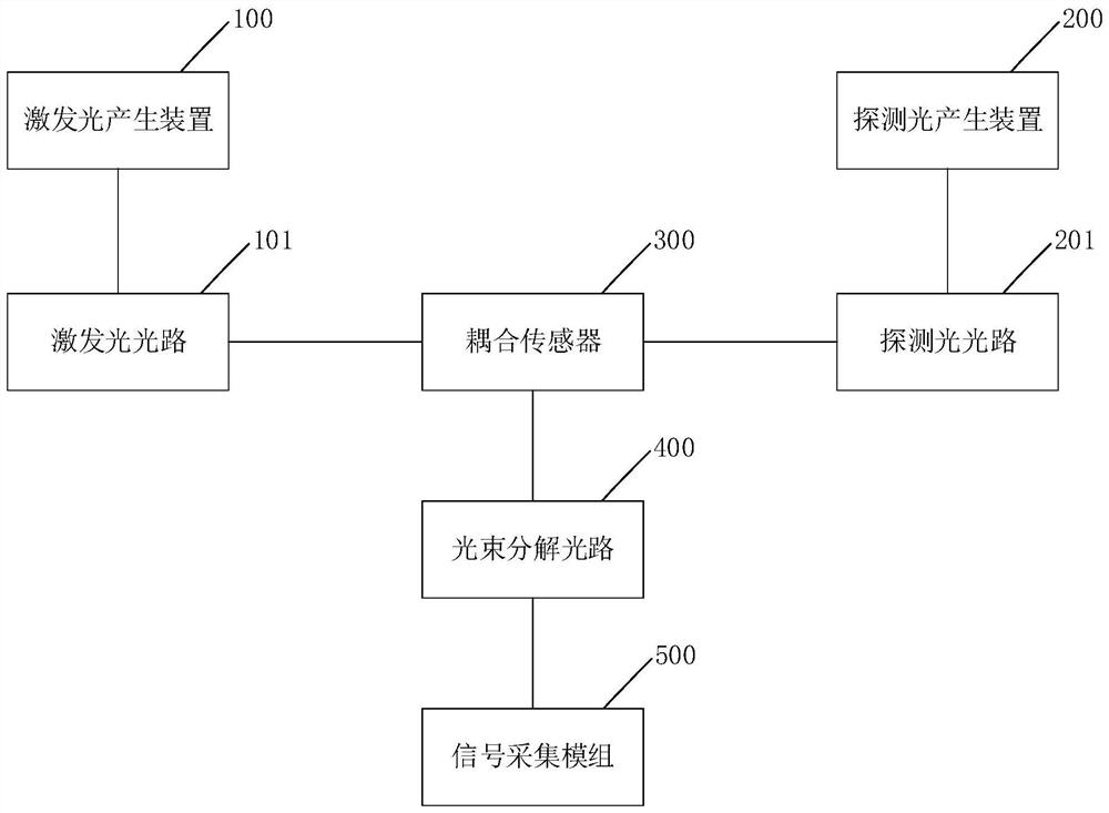
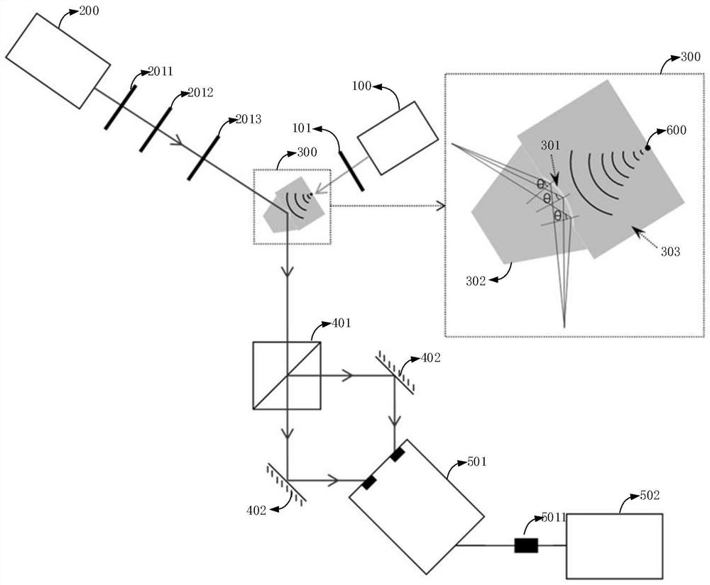
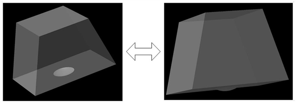
The invention discloses an opto-acoustic microimaging system. The opto-acoustic microimaging system comprises an exciting light generator, an exciting light path, a detection light generator, a detection light path, a coupling sensor, a light beam decomposition light path and a signal acquisition module. The coupling sensor comprises a metal film, a prism with a convex structure, and a liquid medium. Exciting light acts on a to-be-detected object to generate and return opto-acoustic waves, and accordingly, the refractive index of the liquid medium changes along with time. Detection light comprises components S and P. The prism acts on the metal film to trigger surface plasma resonance, absorption of the component P is influenced by modulation of refractive index changes of the liquid medium, and the detection light is refracted by the prism after the strength of the component P is changed. The detection light is decomposed into the component S and the component P, and the time-dependent opto-acoustic signals are generated according to light intensity difference signals to achieve imaging. Compared with the prior art, the opto-acoustic microimaging system has the advantages that thevisual angle for signal detection is widened by the prism with the concave structure, the opto-acoustic signals away from the optical axis can be received, the field of view for imaging is improved,and acquiring and imaging of the opto-acoustic signals in a large field of view are realized.

Description

technical field [0001] The invention relates to the technical field of photoacoustic imaging, in particular to a photoacoustic microscopic imaging system and method. Background technique [0002] Photoacoustic imaging based on the photoacoustic effect has gradually attracted the attention of researchers in recent years. The short-pulse laser is used to irradiate biological tissues, and the pigment substances inside the tissues absorb the energy of the laser, which is produced due to the instantaneous thermoelastic effect. Ultrasonic wave, this ultrasonic wave is the photoacoustic signal. In photoacoustic imaging, there is no need to mark the biological tissue, so as long as the energy of the short pulse laser is controlled within a certain range, it will not cause damage to the biological tissue. Moreover, different biological tissues absorb different short-pulse lasers, so that the specific observation of tissue optical absorption characteristics can be realized. [0003]...

Claims


Application Information

Patent Timeline
Patent Type & Authority Patents(China)
IPC IPC(8): G01N21/17G01N21/552
CPCG01N21/1702G01N21/553
Inventor 彭良亮宋伟闵长俊张崇磊方晖袁小聪
Owner SHEN ZHEN SHEN GUANG SU TECH CO LTD
Learn More