Inflator

A technology of pump and air line, applied in the field of pump, can solve the problems of large volume, single function, inability to carry out easily and so on.

Active Publication Date: 2017-09-19
泉州市弘丰农农业技术有限公司
View PDF6 Cites 0 Cited by
  • Summary
  • Abstract
  • Description
  • Claims
  • Application Information

AI Technical Summary

Problems solved by technology

[0002] The air pump is a device used to inject or supplement the air required by various tires and balls. The air pumps currently used have single functions and large volumes, which cannot be easily carried out, and people need to use both hands when the air pump works. Pressing at the same time is extremely wasteful of energy

Method used


Image

  • Inflator
  • Inflator
  • Inflator

Examples


Embodiment Construction

[0013] The technical solutions in the embodiments of the present invention will be clearly and completely described below in conjunction with the accompanying drawings in the embodiments of the present invention.

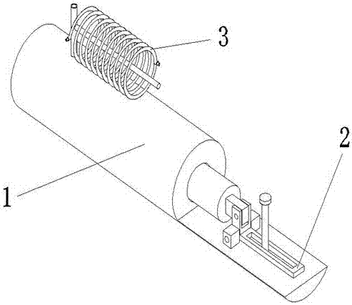
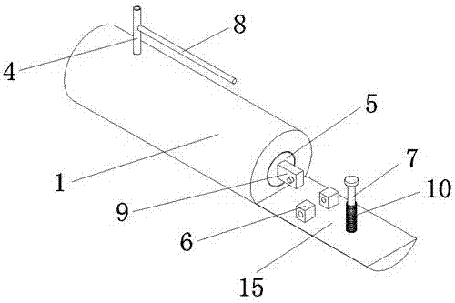
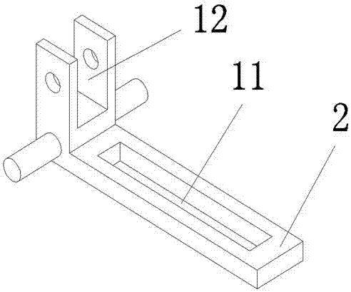
[0014] Such as Figure 1-4 As shown, an inflator includes a main body 1, a lever 2 and a spiral gas line 3. The main body 1 is provided with an air outlet 4, a piston 5 and a handle 15. The air outlet 4 is welded to the outer front end of the main body 1, and the air outlet 4 is The winding rod 8 is welded, the piston 5 is penetrated inside the main body 1, the connecting block 9 is welded at the rear end of the piston 5, the handle 15 is integrally formed and connected to the rear end of the main body 1, and the handle 15 is provided with a supporting block 6 and a guide for connection. The column 7 and the support block 6 are symmetrically welded to the front end above the handle 15, the guide column 7 is welded to the rear end above the handle 15, the guide colum...


PUM


Abstract

The invention discloses an inflator. The inflator comprises a main body, a deflector rod and a spiral air line; the main body is provided with an air outlet, a piston and a handle; the air outlet is welded to the front end of the outer side of the main body, and a line winding rod is welded to the air outlet; the piston is arranged inside the main body in a penetrating mode, and a connection block is welded to the rear end of the piston; the handle is connected to the rear end of the main body in an integrally formed mode and provided with supporting blocks used for connection and a guide column; the deflector rod penetrates through the supporting blocks through a rotary shaft and is provided with a guide groove and a connection groove; the guide groove is formed in the upper portion of the deflector rod, and the guide column is sleeved with the guide groove; the connection groove is formed in the front end of the deflector rod and connected with a connection block through the rotary shaft; and the spiral air line is wound on the line winding rod and provided with a threaded connector for connection, and an air nozzle, and the threaded connector is in threaded connection with the air outlet. The inflator is simple in structure, convenient to maintain and capable of inflating air with one hand, and time and effort are saved.

Description

technical field [0001] The invention relates to an inflator, which belongs to the technical field of inflating equipment. Background technique [0002] The air pump is a device used to inject or supplement the air required by various tires and balls. The air pumps currently used have single functions and large volumes, which cannot be easily carried out, and people need to use both hands when the air pump works. Carry out pressing operation simultaneously, waste physical strength extremely. In order to solve the above problems, a new technical solution is provided. Contents of the invention [0003] The purpose of the present invention is to provide an air pump to solve the problems raised in the background art above. [0004] In order to achieve the above object, the present invention adopts the following technical solutions: an air pump, including a main body, a lever and a spiral gas line, the main body is provided with an air outlet, a piston and a handle, and the ai...

Claims


Application Information

Patent Timeline
IPC IPC(8): F04B33/00F04B39/00
CPCF04B33/00F04B39/00
Inventor 张建
Owner 泉州市弘丰农农业技术有限公司
Why Eureka
Try Eureka