A rolling wheel adjustment auxiliary force bearing mechanism for a furniture sliding door
A rolling wheel and sliding door technology, which is applied in door/window fittings, building structures, and wing leaf suspension devices, etc. It can solve unfavorable door body assembly, failure to meet user needs, and inability to adjust the door body and guide wheels up and down Position and other issues, to improve the effect of sliding opening and closing, improve the effect of sliding opening and closing, and eliminate the difficulty of installation
- Summary
- Abstract
- Description
- Claims
- Application Information
AI Technical Summary
Problems solved by technology
Method used
Image

Examples
no. 1 example
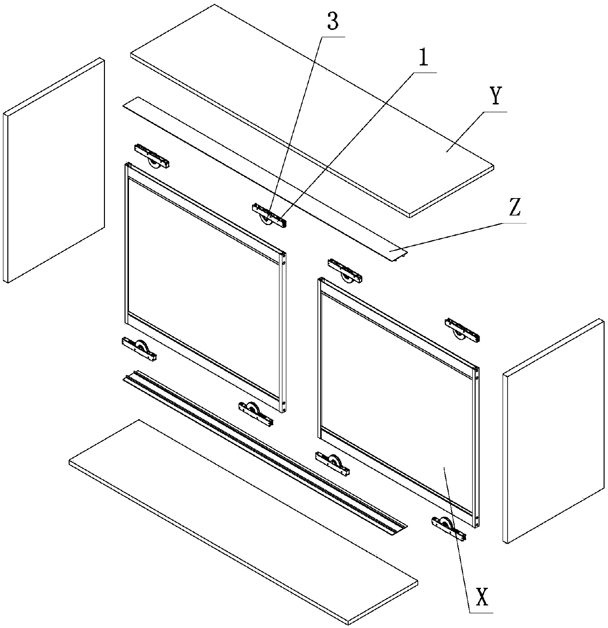
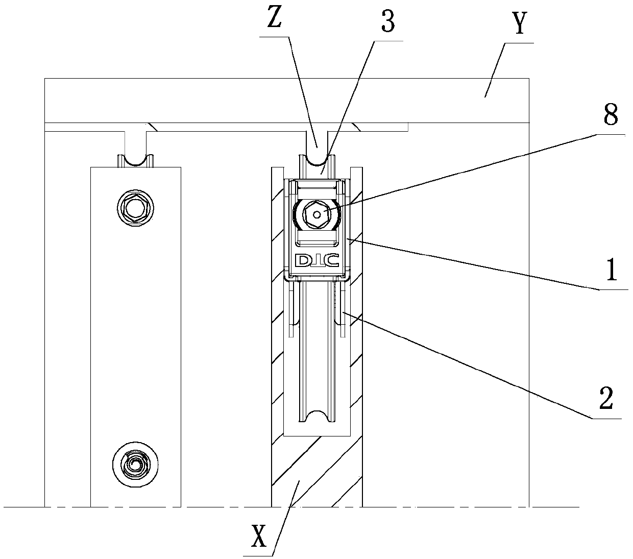
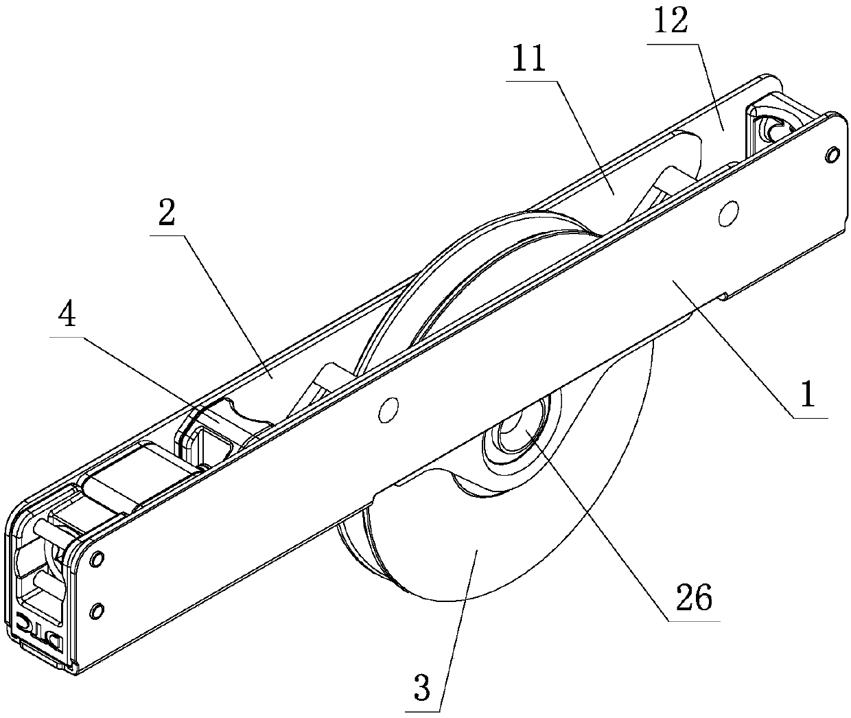
[0023] see Figure 1-Figure 8 , the rolling wheel adjustment auxiliary force bearing mechanism of the sliding door of this furniture includes a fixed bracket 1, a sliding bracket 2 and a rolling wheel 3, the rolling wheel 3 is set on the sliding bracket 2, and the sliding bracket 2 is slidably set on the fixed bracket 1, fixed The bracket 1 is provided with a sliding block 4 and an adjusting assembly, one end of the sliding block 4 is drivingly connected with the adjusting assembly, and is slidably arranged on the fixed bracket 1 through the adjustment of the adjusting assembly, and the other end of the sliding block 4 is mutually driven with the sliding bracket 2; wherein, A supporting and force-bearing fitting part is provided between the sliding block 4 and the sliding bracket 2, and the sliding block 4 and the sliding bracket 2 support each other through the supporting and force-bearing fitting part at least when they are stressed.
[0024] Further, the supporting force fi...
no. 2 example
[0034] see Figure 9 The rolling wheel adjustment auxiliary force bearing mechanism of the furniture sliding door is different from the first embodiment in that at least one longitudinal chute 14 is arranged between the fixed bracket 1 and the sliding bracket 2, and the longitudinal chute 14 is arranged on the On the sliding U-shaped groove 11 of the sliding bracket 2, the fixed bracket 1 is provided with a considerable number of longitudinal guide shafts 16 corresponding to the longitudinal chute 14, and the sliding bracket 2 is longitudinally slid on the longitudinal guide shafts 16 of the fixed bracket 1 through the longitudinal chute 14 superior.
[0035] Adjust the action part 21 through tools or manual action, the adjustment element 8 is positioned and rotated on the fixed bracket 1, and drives the sliding block 4 to perform horizontal linear sliding on the fixed bracket 1 when rotating, and the sliding block 4 drives the swing bar 7 when sliding Swing, the swing rod 7 ...
PUM
 Abstract
Description
Claims
Application Information
 - R&D
- Intellectual Property
- Life Sciences
- Materials
- Tech Scout
- Unparalleled Data Quality
- Higher Quality Content
- 60% Fewer Hallucinations
Browse by: Latest US Patents, China's latest patents, Technical Efficacy Thesaurus, Application Domain, Technology Topic, Popular Technical Reports.
© 2025 PatSnap. All rights reserved.Legal|Privacy policy|Modern Slavery Act Transparency Statement|Sitemap|About US| Contact US: help@patsnap.com