Combined flow hydraulic system in load sensing valve

A load-sensing valve and load-sensing technology, applied in the direction of fluid pressure actuators, servo motors, servo motor components, etc., to achieve the effect of improving drilling efficiency and simple structure

Active Publication Date: 2018-10-26
无锡市钻通工程机械有限公司
View PDF7 Cites 0 Cited by
  • Summary
  • Abstract
  • Description
  • Claims
  • Application Information

AI Technical Summary

Problems solved by technology

There is no requirement for the pump after valve confluence, but an additional reversing valve must be installed

Method used


Image

  • Combined flow hydraulic system in load sensing valve
  • Combined flow hydraulic system in load sensing valve
  • Combined flow hydraulic system in load sensing valve

Examples


Embodiment Construction

[0014] The present invention will be further described below in conjunction with specific drawings.

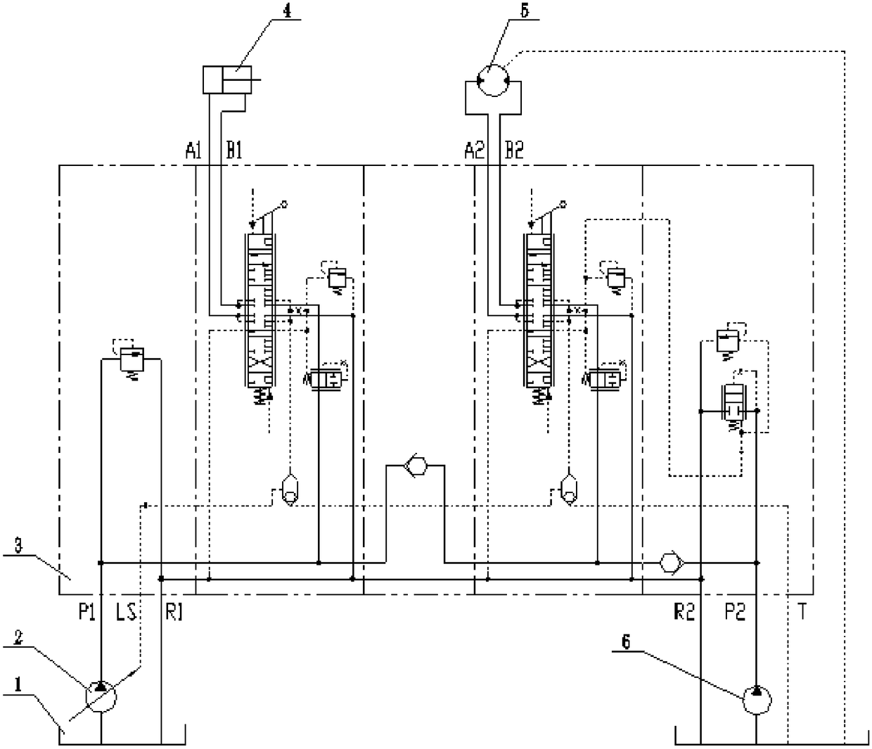
[0015] Such as figure 1 As shown, the confluence hydraulic system in the load sensing valve of the present invention includes a hydraulic oil tank 1, a load sensing variable pump 2, a load sensing proportional multi-way valve 3, a hydraulic cylinder 4, a hydraulic motor 5 and a quantitative pump 6, and a load sensing variable pump 2 The oil suction port of the load-sensing variable pump 2 is connected to the hydraulic oil tank 1, the oil outlet and LS port of the load-sensing variable pump 2 are respectively connected to the P1 port and the LS port of the load-sensing proportional multi-way valve 3, and the oil suction port of the quantitative pump 6 is connected to the hydraulic oil tank 1. The oil outlet of the quantitative pump 6 is connected to the P2 port of the load-sensitive proportional multi-way valve 3, and the A1 port and B1 port of the load-sensitive proportional ...


PUM


Abstract

The invention relates to a load-sensitive in-valve flow converging hydraulic system. The load-sensitive in-valve flow converging hydraulic system is characterized in that a hydraulic oil tank, a load-sensitive variable pump, a load-sensitive proportional multi-way valve, a hydraulic oil cylinder, a hydraulic motor and a constant displacement pump are included; an oil suction opening of the load-sensitive variable pump is connected with the hydraulic oil tank; an oil outlet and an opening LS of the load-sensitive variable pump are connected with an opening P1 and an opening LS of the load-sensitive proportional multi-way valve correspondingly; an oil suction opening of the constant displacement pump is connected with the hydraulic oil tank; an oil outlet of the constant displacement pump is connected with an opening P2 of the load-sensitive proportional multi-way valve; an opening A1 and an opening B1 of the load-sensitive proportional multi-way valve are connected with a rodless cavity and a rod cavity of the hydraulic oil cylinder correspondingly; an opening A2 and an opening B2 of the load-sensitive proportional multi-way valve are connected with an inlet and an outlet of the hydraulic motor correspondingly; and an opening R1, an opening R2 and an opening T of the load-sensitive proportional multi-way valve and an oil drain opening of the hydraulic motor are connected with the hydraulic oil tank. According to the load-sensitive in-valve flow converging hydraulic system, a loop formed by the load-sensitive proportional multi-way valve is adopted for achieving flow converging of the variable pump and the constant displacement pump in the load-sensitive proportional multi-way valve.

Description

technical field [0001] The invention relates to a load-sensing valve in-valve confluence hydraulic system, in particular to a valve in-valve confluence system of a variable pump and a quantitative pump, and belongs to the technical field of hydraulic equipment. Background technique [0002] The hydraulic system is divided into two categories: open system and closed system, and the open system is divided into variable pump system and quantitative pump system. Due to the limitation of hydraulic pump displacement, when a large flow is required, a multi-pump confluence system is often used. At present, the mainstream confluence system is divided into two types, the pre-valve confluence (such as image 3 as shown), post-valve confluence (such as Figure 4 shown). [0003] When using pre-valve confluence, the double pumps must be both variable variable pumps or fixed fixed pumps. There is no requirement for the pump to flow after the valve, but an additional reversing valve mus...

Claims


Application Information

Patent Timeline
Patent Type & Authority Patents(China)
IPC IPC(8): F15B11/17F15B13/06
CPCF15B11/161F15B11/17F15B2013/002F15B2211/20576F15B2211/78
Inventor 徐彬彬于峰贾绍宽
Owner 无锡市钻通工程机械有限公司
Why Eureka
Try Eureka