Mining dump truck hydraulic system

A technology of mining dump truck and hydraulic system, applied in the field of hydraulic system, can solve the problems of erratic steering, increased pressure, affecting the life of components, etc., and achieves the effects of simple control method, simplified steering performance, and reduced cost

Active Publication Date: 2015-12-23
GUANGXI LIUGONG MASCH CO LTD
View PDF9 Cites 0 Cited by
  • Summary
  • Abstract
  • Description
  • Claims
  • Application Information

AI Technical Summary

Problems solved by technology

[0006] (2) For the hydraulic system shown on the right, although the priority valve is canceled, the stability of the steering system is not guaranteed, and when the steering operation is performed, all the flow of the steering pump enters the steering system and the flow of the steering cylinder The amount of oil is determined by the speed of the engine. The higher the speed, the greater the flow, which makes the steering erratic. All the excess flow of the steering pump flows back to the fuel tank through the high-pressure overflow of the steering relief valve, causing serious energy loss, and the frequent opening of the relief valve Will seriously affect component life
[0007] (3) When the mining dump truck is performing unloading operations, when the center of gravity of the cargo and container exceeds the installation hinge point between the multi-stage cylinder and the container, the cargo and container will drop rapidly under the action of gravity. If the hydraulic system gives Insufficient oil supply of multi-stage cylinders will cause negative pressure in the large cavity of the cylinder, and the pressure in the small cavity will increase instantaneously due to extrusion, which will cause the hydraulic system to work unstable

Method used


Image

  • Mining dump truck hydraulic system
  • Mining dump truck hydraulic system
  • Mining dump truck hydraulic system

Examples


Embodiment Construction

[0020] The specific implementation will be described below in conjunction with the accompanying drawings.

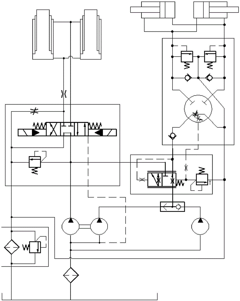
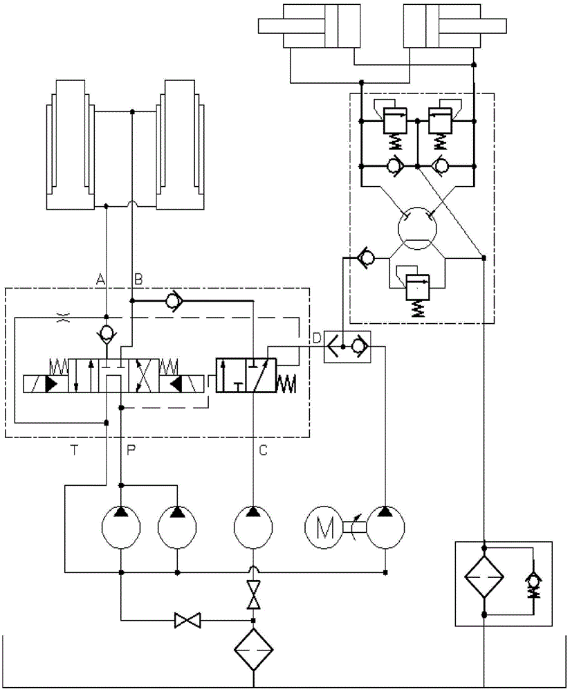
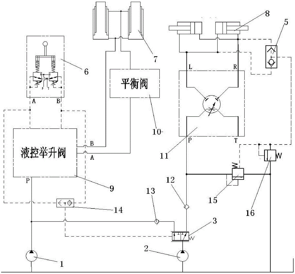
[0021] Such as image 3 As shown, in this embodiment, the mining dump truck hydraulic system includes a hydraulic steering system and a lifting system, and the hydraulic lifting system includes a lifting cylinder 7, a hydraulically controlled lifting valve 9, a pilot valve 6, a balance valve 10, a lifting Lifting pump 1, the lifting pump is connected to the P port of the hydraulic control lift valve, the pilot valve 6 is connected to the control oil port of the hydraulic control lift valve 9, and the A port and B port of the hydraulic control lift valve 9 are connected to the lifting cylinder Connection, the balance valve 10 is connected between the hydraulic control lift valve 9 and the lift cylinder 7;

[0022] The hydraulic steering system includes a steering cylinder 8, a steering pump 2, a steering gear 11, a differential pressure reducing valve 15, a shuttle valve...


PUM


Abstract

The invention relates to a hydraulic system of a mining dump truck. A hydraulic steering system in the hydraulic system of the mining dump truck comprises a steering oil cylinder, a hydraulic power oil source and a steering gear, wherein the steering gear is connected with the steering oil cylinder, and the hydraulic power oil source is connected with a port P of the steering gear. The hydraulic steering system further comprises a uniform-pressure-drop valve and a first shuttle valve, an oil inlet of the uniform-pressure-drop valve is communicated with the port P of the steering gear, an oil outlet of the uniform-pressure-drop valve is communicated with an oil tank loop, a pressure control oil port of the uniform-pressure-drop valve is communicated with an oil outlet of a shuttle valve, and two oil inlets of the shuttle valve are communicated with a port L and a port R of the steering gear respectively. According to the hydraulic system of the mining dump truck, the steering gear and a pilot valve are not in combined use, an overflow speed regulating loop is formed by connecting the uniform-pressure-drop valve to the inlet and the outlet of the steering gear, steering performance is ensured, the structure is simplified, and certain cost can be reduced. Converging of lifting and the hydraulic steering system is achieved in lifting, and energy consumption is reduced.

Description

technical field [0001] The invention relates to a hydraulic system, in particular to a hydraulic steering system for mining dump trucks. Background technique [0002] Mining dump truck is a heavy-duty truck used to complete ore transportation tasks in open-pit mines. It is characterized by short transportation distances and strong carrying capacity. Excavation yards and unloading yards are widely used in metallurgy, non-ferrous metals, chemicals, coal and other earthwork transportation industries. Mining dump trucks are mainly composed of power system, transmission system, frame, cargo box, suspension system, steering system, hydraulic system, braking system, electrical system and covering parts. At present, the tonnage of mining dump trucks ranges from 20 tons Generally, the tonnage of mine trucks used in mines is in line with its output. For small mines with an annual output of one million tons, 25-50 tons of vehicles are used; for mines with an annual output of 5-10 mill...

Claims


Application Information

Patent Timeline
Patent Type & Authority Patents(China)
IPC IPC(8): B62D5/06B60P1/16
Inventor 杨胜清王玉唐绪文唐云娟
Owner GUANGXI LIUGONG MASCH CO LTD
Why Eureka
Try Eureka