
Motor grader front wheel drive control valve and hydraulic system

A front-wheel drive, hydraulic system technology, applied in mechanically driven excavators/dredgers, control devices, mechanical equipment, etc., can solve problems affecting straight-line operation and steering performance, etc., to ensure straight-line operation and steering performance, improve The effect of work efficiency and economy

Active Publication Date: 2020-06-09
GUANGXI LIUGONG MASCH CO LTD
View PDF5 Cites 0 Cited by
  • Summary
  • Abstract
  • Description
  • Claims
  • Application Information

AI Technical Summary

Problems solved by technology

[0007] The technical problem to be solved by the present invention is to provide a front-wheel drive that can select different working mode modes according to the conditions of the working ground, and can The motor grader front wheel drive control valve and hydraulic system can flexibly and effectively play the role of front wheel power assist and improve the working efficiency and economy of the whole machine

Method used


Image

  • Motor grader front wheel drive control valve and hydraulic system
  • Motor grader front wheel drive control valve and hydraulic system
  • Motor grader front wheel drive control valve and hydraulic system

Examples


Embodiment Construction

[0021] The specific implementation will be described below in conjunction with the accompanying drawings.

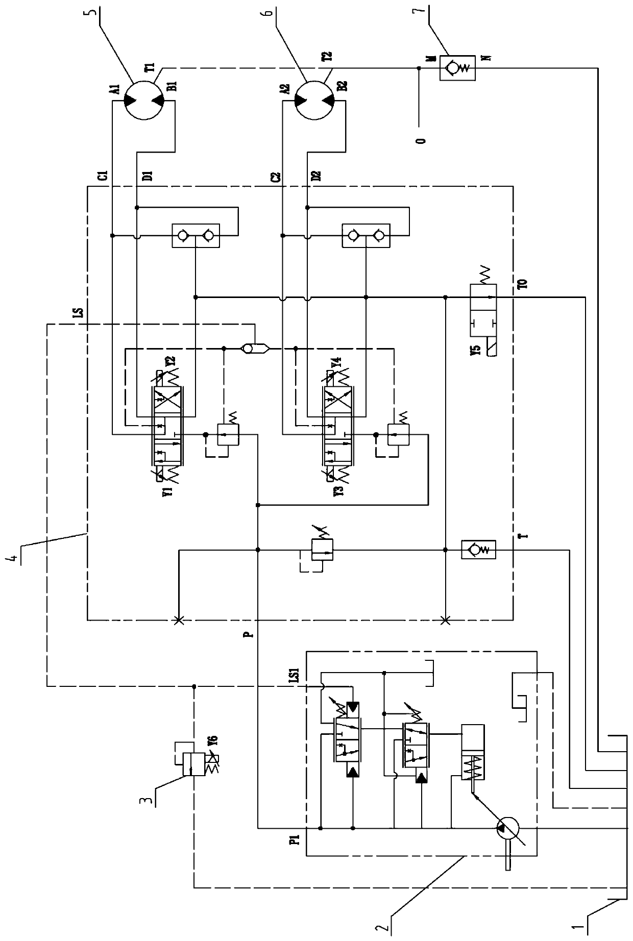
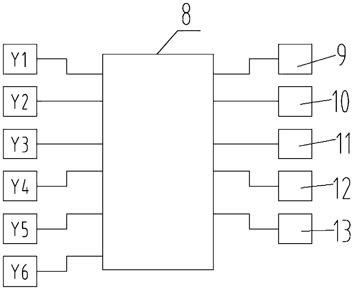
[0022] Such as figure 1 , image 3 As shown, the hydraulic system for driving the front wheels of the grader in this embodiment includes a hydraulic oil tank 1, a drive pump 2, a working mode selection valve 3, a control valve for driving the front wheels of the grader 4, a left front wheel hydraulic motor 5, and a right front wheel Hydraulic motor 6, back pressure valve 7, controller 8, rear wheel speed sensor 9, working mode input device 10, rotation angle sensor device 11, engine speed sensor 12, working condition mode input device 13.

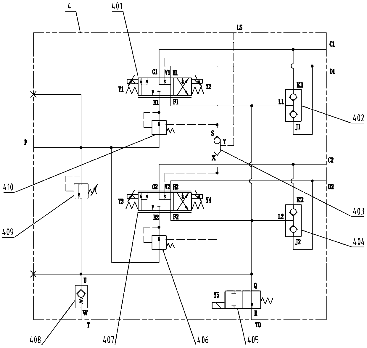
[0023] Such as figure 2 As shown, the motor grader front wheel drive control valve 4 includes a left front wheel control valve 401, a first two-way oil supply valve 402, a shuttle valve 403, a second two-way oil supply valve 404, a mode switching valve 405, a right compensation valve 406, a right Front wheel control valve 407, oil...


PUM


Abstract

The invention relates to land leveler front-wheel drive and provides a land leveler front-wheel driving hydraulic system in order to solve the problems that a unilateral wheel of front wheels slips easily and affects linear operation and steering performance during existing land leveler front-wheels driving. The land leveler front-wheel driving hydraulic system comprises a land leveler front-wheeldriving control valve. A variable pump is connected with an oil port P of the land leveler front-wheel driving control valve through a pipe. An oil port C1, an oil port D1, an oil port C2 and an oilport D2 of the land leveler front-wheel driving control valve are connected with working oil ports of left and right front-wheel hydraulic motors correspondingly. An oil port LS of the land leveler front-wheel driving control valve is connected with a load feedback port of the variable pump. An oil port T of the land leveler front-wheel driving control valve and an oil inlet of the variable pump are connected with a hydraulic oil tank through pipes. In the hydraulic system, the left and right front wheels are controlled independently to avoid unilateral slippage, and linear operation and the steering performance to the land leveler can be guaranteed. The land leveler front-wheel driving hydraulic system can select different working condition modes according to the operation ground conditions and can flexibly and effectively achieve the assistance effect of the front wheels and improve the operation efficiency and economic efficiency of a whole machine.

Description

technical field [0001] The invention relates to a front wheel drive of a grader, more specifically, a control valve and a hydraulic system for the front wheel drive of a grader. Background technique [0002] The existing motor grader front wheel drive system is a front wheel power-assisted open hydraulic system with a drive pump and two motors. The drive pump absorbs oil from the hydraulic oil tank, and the outlet pressure oil is directly connected to the two parallel motors after passing through the control valve, and then through the control valve. An open hydraulic system back to the hydraulic tank. The flow of hydraulic oil entering the motor is determined by the opening of the spool of the three-position four-way reversing valve inside the control valve, and the pressure of the system is determined by the pressure cut-off valve of the driving pump. [0003] When the motor grader starts to work, the displacement of the drive pump is at the maximum displacement, and the ...

Claims


Application Information

Patent Timeline
Patent Type & Authority Patents(China)
IPC IPC(8): F15B11/16E02F3/85B60K17/356
CPCB60K17/356E02F3/84F15B11/165F15B2211/20546F15B2211/255F15B2211/405F15B2211/6336
Inventor 刘光喜李良周白健信李大尤
Owner GUANGXI LIUGONG MASCH CO LTD
Learn More